Data modeling is a critical technique used to document a software system using Entity-Relationship Diagrams (ERDs). These diagrams provide a powerful representation of a company’s business requirements and serve as a guide for database analysts and software developers in the design and implementation of a system and its underlying database. This article explores the different levels of data models—conceptual, logical, and physical—and provides examples to illustrate their use.
What is an Entity-Relationship Diagram (ERD)?
An Entity-Relationship Diagram (ERD) is a pictorial representation of the information that can be captured by a database. It serves two primary purposes:
- Design Documentation: Allows database professionals to describe an overall design concisely yet accurately.
- Schema Transformation: Can be easily transformed into a relational schema.
Components of an ERD
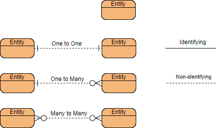
- Entities: The basic objects of ERDs, representing the tables in a database (e.g., students, courses, books).
- Attributes: Facts or descriptions of entities, becoming the columns of the table (e.g., first name, last name, email).
- Relationships: Associations between entities, often described by verbs (e.g., a student enrolls in a course).
Key Concepts
- Primary Key: An attribute or set of attributes that uniquely identifies an instance of the entity.
- Foreign Key: A key used to link two tables together, typically the primary key from one table inserted into another.
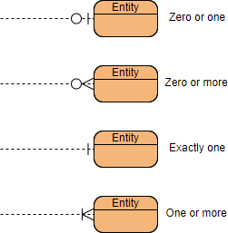
- Cardinality: Defines the possible number of occurrences in one entity associated with another (e.g., one-to-one, one-to-many, many-to-many).
ERD Example: Customer Appointment
Consider a business scenario where:
- One Customer may make one or more Appointments.
- One Appointment must be made by one and only one Customer.
The cardinality linked from Customer to Appointments is one-to-many.
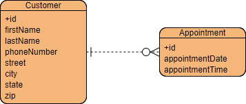
Simple ERD Example
In the ERD above, using Crow’s Foot notation:
- Entities are shown in boxes with attributes listed below the entity name.
- Relationships are shown as solid lines between two entities.
- Cardinality is represented with either a straight line and hash marks or a crow’s foot.
Conceptual, Logical, and Physical Data Models
Data models are typically represented at three levels of abstraction: conceptual, logical, and physical. Each level serves a different purpose and targets a different audience.
Conceptual Data Model
The conceptual data model establishes the entities, their attributes, and their relationships. It presents an overall picture of the system by recognizing the business objects involved. This model defines what entities exist without specifying the tables.
Characteristics
- Entities: Yes
- Relationships: Yes
- Columns: Yes
- Column’s Type: Optional
- Primary Key: No
- Foreign Key: No
Example
A conceptual ERD might show entities like Customer and Appointment with a one-to-many relationship, without specifying column types or keys.
Logical Data Model
The logical data model defines the structure of the data elements and sets the relationships between them. It enriches the conceptual model by explicitly defining the columns in each entity and introducing operational and transactional entities.
Characteristics
- Entities: Yes
- Relationships: Yes
- Columns: Yes
- Column’s Type: Optional
- Primary Key: No
- Foreign Key: No
Example
A logical ERD might include entities like Customer and Appointment with attributes such as CustomerID, AppointmentID, Date, and Time, but without specifying data types.
Physical Data Model
The physical data model represents the actual design blueprint of a relational database. It elaborates on the logical data model by assigning each column a type, length, nullability, etc. This model considers the conventions and restrictions of the specific DBMS in which the database will be created.
Characteristics
- Entities: Yes
- Relationships: Yes
- Columns: Yes
- Column’s Type: Yes
- Primary Key: Yes
- Foreign Key: Yes
Conceptual model vs Logical model vs Data model:
| ERD feature | Conceptual | Logical | Physical |
|---|---|---|---|
| Entity (name) | Yes | Yes | Yes |
| Relationship | Yes | Yes | Yes |
| Column | Yes | Yes | |
| Column’s Type | Optional | Yes | |
| Primary Key | Yes | ||
| Foreign Key | Yes |
Example
A physical ERD might include entities like Customer and Appointment with attributes such as CustomerID (INT, PK), AppointmentID (INT, PK), Date (DATE), and Time (TIME), with specified data types and keys.
Conceptual data model
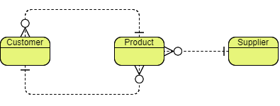
Conceptual ERD models the business objects that should exist in a system and the relationships between them. A conceptual model is developed to present an overall picture of the system by recognizing the business objects involved. It defines what entities exist, NOT which tables. For example, ‘many to many’ tables may exist in a logical or physical data model but they are just shown as a relationship with no cardinality under the conceptual data model.
Conceptual data model example
NOTE: Conceptual ERD supports the use of generalization in modeling the ‘a kind of’ relationship between two entities, for instance, Triangle, is a kind of Shape. The usage is like generalization in UML. Notice that only conceptual ERD supports generalization.
Logical data model
Logical ERD is a detailed version of a Conceptual ERD. A logical ER model is developed to enrich a conceptual model by defining explicitly the columns in each entity and introducing operational and transactional entities. Although a logical data model is still independent of the actual database system in which the database will be created, you can still consider that if it affects the design.
Logical data model example

Physical data model
Physical ERD represents the actual design blueprint of a relational database. A physical data model elaborates on the logical data model by assigning each column with type, length, nullable, etc. Since a physical ERD represents how data should be structured and related in a specific DBMS it is important to consider the convention and restriction of the actual database system in which the database will be created. Make sure the column types are supported by the DBMS and reserved words are not used in naming entities and columns.
Physical data model example
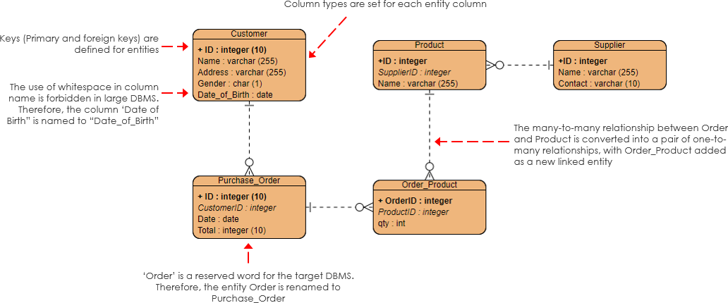
Edit this physical ERD example
The Ideal ER Modeling Tool for Software Development Teams
In the realm of software development, effective data modeling is crucial for designing robust and efficient databases. Entity-Relationship (ER) modeling is a fundamental technique used to visualize and plan the data structures that underpin applications. Among the various tools available for ER modeling, Visual Paradigm stands out as an ideal choice for software development teams. Here’s why:
Comprehensive Modeling Capabilities
Visual Paradigm offers a comprehensive suite of tools for creating Conceptual, Logical, and Physical ER diagrams. This allows teams to progress seamlessly from high-level business requirements to detailed database schemas ready for implementation. The ability to transition between these levels of abstraction ensures that the final database design is both accurate and aligned with business needs.
User-Friendly Interface
One of the standout features of Visual Paradigm is its intuitive and user-friendly interface. The drag-and-drop functionality makes it easy to add entities, attributes, and relationships, streamlining the modeling process. This accessibility is particularly beneficial for teams with varying levels of technical expertise, enabling everyone to contribute effectively to the data modeling process.
Advanced Features
Visual Paradigm is packed with advanced features that enhance the ER modeling experience:
- Data Types and Constraints: Define data types, primary keys, foreign keys, and constraints to ensure that your Physical ERD is ready for database implementation.
- SQL Generation: Automatically generate SQL scripts from your Physical ERD, facilitating the creation of the database schema in your chosen DBMS.
- Design Traceability: Track the origin of design elements, allowing new team members to understand the project’s foundations and ensuring the integrity of the design throughout the development lifecycle.
Collaboration and Documentation
Effective collaboration is essential for successful software development. Visual Paradigm supports collaborative work, enabling multiple users to work on the same project simultaneously. This feature is invaluable for large-scale projects involving multiple stakeholders. Additionally, the tool provides robust documentation features, allowing teams to keep detailed records of design decisions, changes, and rationales.
Integration and Compatibility
Visual Paradigm is compatible with a wide range of DBMSs, ensuring that your Physical ERD adheres to the conventions and restrictions of your target database system. The tool also supports importing and exporting models in various formats, making it easy to integrate with other tools and systems used in your development environment.
Customization and Flexibility
Every project has unique requirements, and Visual Paradigm offers the flexibility to tailor your ER diagrams to meet those needs. Customizable templates and the ability to add, modify, and delete entities, attributes, and relationships ensure that your data models evolve with your project requirements.
Learning and Support
Visual Paradigm provides extensive documentation and tutorials to help users get up to speed quickly. The tool also comes with excellent customer support, ensuring that you have access to help and guidance whenever you need it. This support is crucial for teams looking to maximize the benefits of ER modeling and achieve successful database implementations.
Conclusion
The main goal of data modeling is to ensure that the data objects provided by the functional team are represented accurately. The process typically starts with a conceptual data model, which is refined into a logical model as more information becomes available. Finally, when the implementation details are known, the logical model is refined into a physical data model, which can be directly mapped to the actual database system.
By understanding and utilizing conceptual, logical, and physical data models, database analysts and software developers can create robust, efficient, and implementable database designs that meet the business requirements of their organizations.
Visual Paradigm is the ideal ER modeling tool for software development teams, offering a comprehensive set of features that streamline the data modeling process. From its user-friendly interface and advanced features to its collaboration capabilities and integration with various DBMSs, Visual Paradigm provides everything needed to create robust, efficient, and implementable database designs. By leveraging Visual Paradigm, software development teams can ensure that their data models accurately reflect business requirements and support the successful implementation of their applications.

