Introduction
In this case study, we will explore the component diagram for an e-commerce system. The component diagram is a type of UML (Unified Modeling Language) diagram that shows the structural relationships between the components of a system. It provides a high-level view of the system’s architecture, highlighting the key components and their interactions.

Key Concepts
Before diving into the case study, let’s review some key concepts related to component diagrams:
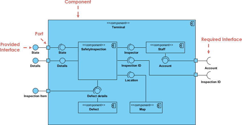
- Component: A modular part of a system that encapsulates its implementation and provides a well-defined interface for interaction with other components.
- Interface: A contract that specifies the operations a component provides or requires.
- Port: A connection point between a component and its environment, representing a point of interaction.
- Connector: A link between components or ports, representing a communication path.
- Dependency: A relationship indicating that one component depends on another.
- Assembly Connector: A connector that represents the assembly of components, often depicted as a ball-and-socket.
- Delegation Connector: A connector that represents the delegation of responsibilities from one component to another.
Case Study: E-commerce System
System Overview
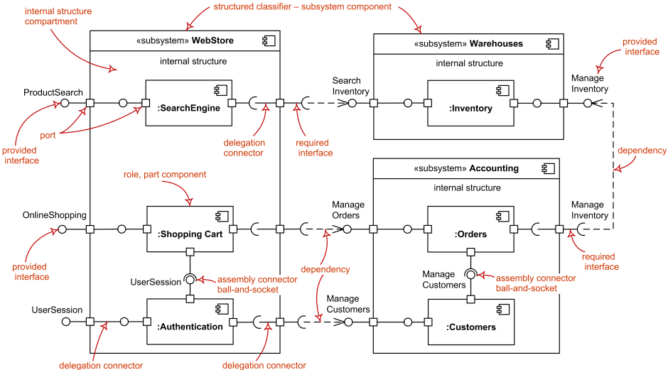
The e-commerce system consists of three main subsystems: WebStore, Warehouses, and Accounting. Each subsystem contains several components that interact to provide the system’s functionality.

Component Diagram Analysis
Subsystems and Components
- WebStore Subsystem:
- SearchEngine: Responsible for searching products.
- ShoppingCart: Manages the user’s shopping cart.
- Authentication: Handles user authentication.
- Warehouses Subsystem:
- Inventory: Manages the inventory of products.
- Accounting Subsystem:
- Orders: Manages customer orders.
- Customers: Manages customer information.
Interfaces and Ports
- Provided Interfaces:
- ProductSearch: Interface provided by the SearchEngine component for searching products.
- OnlineShopping: Interface provided by the ShoppingCart component for online shopping.
- UserSession: Interface provided by the Authentication component for managing user sessions.
- ManageInventory: Interface provided by the Inventory component for managing inventory.
- ManageOrders: Interface provided by the Orders component for managing orders.
- ManageCustomers: Interface provided by the Customers component for managing customer information.
- Required Interfaces:
- SearchInventory: Interface required by the SearchEngine component to search the inventory.
- ManageOrders: Interface required by the ShoppingCart component to manage orders.
- ManageCustomers: Interface required by the ShoppingCart component to manage customer information.
- ManageInventory: Interface required by the Orders component to manage inventory.
Connectors
- Delegation Connectors:
- The SearchEngine component delegates the search inventory task to the Inventory component.
- The ShoppingCart component delegates the manage orders and manage customers tasks to the Orders and Customers components, respectively.
- The Authentication component delegates the manage customers task to the Customers component.
- Assembly Connectors:
- The ShoppingCart component is assembled with the Orders component using a ball-and-socket connector.
- The Authentication component is assembled with the Customers component using a ball-and-socket connector.
- Dependency:
- The SearchEngine component depends on the Inventory component.
- The ShoppingCart component depends on the Orders and Customers components.
- The Orders component depends on the Inventory component.
Guidelines for Creating Component Diagrams
- Identify Key Components: Start by identifying the key components of the system and their responsibilities.
- Define Interfaces: Define the interfaces provided and required by each component.
- Establish Connectors: Establish the connectors between components, including delegation and assembly connectors.
- Show Dependencies: Show the dependencies between components to highlight their relationships.
- Use Clear Labels: Use clear and descriptive labels for components, interfaces, and connectors.
- Keep It Simple: Keep the diagram simple and focused on the high-level architecture. Avoid including too much detail.
Conclusion
The component diagram for the e-commerce system provides a clear and concise view of the system’s architecture. It highlights the key components, their interfaces, and their interactions. By following the guidelines for creating component diagrams, you can effectively communicate the structural design of a system to stakeholders.
Reference List on UML Component Diagram, Visual Paradigm
- How to Draw Component Diagram?
- URL: How to Draw Component Diagram?
- Description: A step-by-step guide on creating a UML component diagram in Visual Paradigm, covering the basics and advanced techniques for modeling software components.
- What is Component Diagram?
- URL: What is Component Diagram?
- Description: An introductory guide to component diagrams, explaining their purpose and how they are used to model the static implementation view of a system.
- UML Practical Guide – All you need to know about UML modeling
- URL: UML Practical Guide
- Description: A comprehensive guide to UML modeling, including component diagrams, which are used to describe the static deployment view of a system.
- Component Diagram Tutorial
- URL: Component Diagram Tutorial
- Description: A detailed tutorial on component diagrams, including examples and tips on how to create them using Visual Paradigm Online.
- Mastering the Art of UML Component Diagrams: A Guide to Software Architecture Modeling and Design
- URL: Mastering the Art of UML Component Diagrams
- Description: An in-depth guide to using UML component diagrams for software architecture modeling and design, highlighting their importance in software engineering.
- Component diagram in Visual Paradigm
- URL: Component diagram in Visual Paradigm
- Description: A chapter from the Visual Paradigm user guide that focuses on creating component diagrams, explaining their role in modeling the physical aspects of software systems.
- How to Draw a Component Diagram in UML?
- URL: How to Draw a Component Diagram in UML?
- Description: A tutorial on drawing UML component diagrams, including steps and examples to help users understand the process.
- Component Diagram – UML 2 Diagrams – UML Modeling Tool
- URL: Component Diagram – UML 2 Diagrams
- Description: An overview of component diagrams in UML 2, highlighting their role in illustrating the architectures of software components and their dependencies.
- Beginner’s Guide to Component Diagrams in UML
- URL: Beginner’s Guide to Component Diagrams in UML
- Description: A beginner-friendly guide to component diagrams in UML, including key concepts and steps for creating them using Visual Paradigm Online.

