1. Introduction
1.1 Overview of Sequence Diagrams
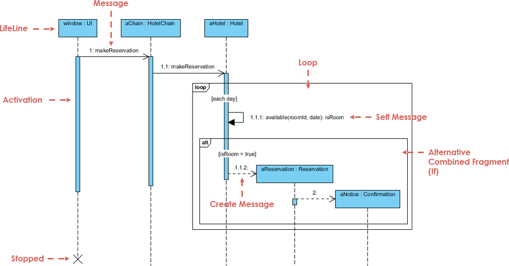
Sequence diagrams are a crucial component of the Unified Modeling Language (UML), providing a visual representation of how objects interact in a particular scenario of a use case. They are particularly useful for modeling the dynamic aspects of a system, showing how objects communicate over time. This article aims to provide a comprehensive guide to understanding, creating, and utilizing sequence diagrams effectively in software development.
1.2 Importance in UML Modeling
Sequence diagrams play a vital role in UML modeling by capturing the interaction between objects in a system. They help in understanding the flow of control and data between different components, making them essential for designing and documenting system behavior. By visualizing the sequence of messages exchanged between objects, sequence diagrams facilitate better communication among stakeholders and ensure that the system meets the specified requirements.
2. Understanding Sequence Diagrams
2.1 Basic Concepts
Sequence diagrams focus on the time ordering of messages exchanged between objects. They provide a visual representation of how objects interact over time, making them an essential tool for modeling dynamic behaviors in a system.
2.2 Key Components
2.2.1 Actors
Actors represent external entities that interact with the system. They can be users, other systems, or hardware devices. Actors initiate interactions with the system and receive responses from it.
2.2.2 Lifelines
Lifelines represent the existence of an object over time. They are depicted as dashed lines that show the duration of an object’s participation in the interaction.
2.2.3 Messages
Messages represent communication between objects. They can be synchronous, asynchronous, or return messages, indicating the type of interaction between objects.
2.2.4 Activation Bars
Activation bars represent the duration of an object’s participation in a specific operation. They are depicted as thin rectangles on the lifeline, showing when an object is active in the interaction.
2.3 Types of Messages
2.3.1 Synchronous Messages
Synchronous messages represent a call to an operation where the sender waits for the receiver to complete the operation before continuing. They are depicted as solid arrows with a filled arrowhead.
2.3.2 Asynchronous Messages
Asynchronous messages represent a call to an operation where the sender does not wait for the receiver to complete the operation. They are depicted as solid arrows with an open arrowhead.
2.3.3 Return Messages
Return messages represent the return of control from the receiver to the sender after completing an operation. They are depicted as dashed arrows with an open arrowhead.
3. Creating Sequence Diagrams
3.1 Step-by-Step Guide
3.1.1 Identifying Participants
The first step in creating a sequence diagram is to identify the participants involved in the interaction. Participants can be actors or objects that play a role in the scenario being modeled.
3.1.2 Defining Interactions
The next step is to define the interactions between participants. This involves identifying the messages exchanged between objects and the sequence in which they occur.
3.1.3 Drawing the Diagram
Once the participants and interactions are identified, the sequence diagram can be drawn. This involves depicting the lifelines, messages, and activation bars to represent the interaction visually.
3.2 Best Practices
- Use Clear Naming Conventions: Ensure that the names of participants and messages are clear and consistent.
- Keep It Simple: Avoid overcomplicating the diagram by including only the essential interactions.
- Use Comments: Add comments to the diagram to explain complex interactions or provide additional context.
3.3 Common Mistakes to Avoid
- Overloading the Diagram: Including too many details can make the diagram difficult to understand.
- Inconsistent Naming: Using inconsistent names for participants and messages can lead to confusion.
- Ignoring Edge Cases: Failing to consider edge cases can result in an incomplete understanding of the system’s behavior.
4. Use Cases and Applications
4.1 Modeling System Interactions
Sequence diagrams are commonly used to model the interactions between different components of a system. They help in understanding how objects communicate and collaborate to achieve a specific goal.
4.2 Designing Software Architecture
In software architecture, sequence diagrams are used to design the interaction between software components. They help in identifying the responsibilities of each component and ensuring that the system meets the specified requirements.
4.3 Documenting System Behavior
Sequence diagrams are also used to document the behavior of a system. They provide a visual representation of how the system responds to different inputs and interactions, making them useful for documentation and communication.
4.4 Case Studies
Several case studies demonstrate the application of sequence diagrams in real-world scenarios. These case studies provide insights into how sequence diagrams can be used to model and design complex systems effectively.
5. Advanced Features of Sequence Diagrams
5.1 Combined Fragments
Combined fragments are used to represent complex interaction patterns in sequence diagrams. They include alternatives, options, loops, and parallel interactions.
5.1.1 Alternatives
Alternatives represent different paths that the interaction can take based on certain conditions. They are depicted using the “alt” keyword.
5.1.2 Options
Options represent optional interactions that may or may not occur. They are depicted using the “opt” keyword.
5.1.3 Loops
Loops represent repetitive interactions that occur multiple times. They are depicted using the “loop” keyword.
5.1.4 Parallel
Parallel represents interactions that occur simultaneously. They are depicted using the “par” keyword.
5.2 Interaction Uses
Interaction uses represent the inclusion of one interaction diagram within another. They are depicted using the “ref” keyword and help in reusing interaction patterns across multiple diagrams.
5.3 Interaction Occurrences
Interaction occurrences represent the invocation of an interaction from another interaction. They are depicted using the “sd” keyword and help in modeling complex interaction patterns.
6. Integration with Other UML Diagrams
6.1 Use Case Diagrams
Sequence diagrams can be integrated with use case diagrams to provide a detailed view of the interactions that occur within a use case. They help in understanding the dynamic behavior of the system from the user’s perspective.
6.2 Class Diagrams
Sequence diagrams can be integrated with class diagrams to show how the classes in the system interact with each other. They help in understanding the relationship between the static structure and dynamic behavior of the system.
6.3 Activity Diagrams
Sequence diagrams can be integrated with activity diagrams to provide a detailed view of the workflow within the system. They help in understanding the sequence of activities and the interactions that occur between them.
6.4 State Machine Diagrams
Sequence diagrams can be integrated with state machine diagrams to show how the states of an object change in response to interactions. They help in understanding the dynamic behavior of the system from the perspective of an object’s lifecycle.
7. Tools and Technologies
7.1 Popular UML Tools
Several popular UML tools support the creation of sequence diagrams, including Visual Paradigm, Enterprise Architect, and Lucidchart. These tools provide a range of features for creating, editing, and sharing sequence diagrams.
7.2 Choosing the Right Tool
Choosing the right UML tool depends on various factors, including ease of use, features, integration with other tools, and cost. It is essential to select a tool that meets the specific needs of the project and the team.
7.3 Integration with Development Environments
Integrating UML tools with development environments such as Eclipse, Visual Studio, and IntelliJ IDEA can enhance productivity and ensure consistency between the design and implementation of the system.
8. Challenges and Solutions
8.1 Handling Complexity
Handling the complexity of sequence diagrams can be challenging, especially in large systems with many interactions. Using combined fragments and interaction uses can help in managing complexity and making the diagrams more understandable.
8.2 Ensuring Accuracy
Ensuring the accuracy of sequence diagrams is crucial for effective communication and documentation. Using clear naming conventions, consistent notation, and validation tools can help in ensuring the accuracy of the diagrams.
8.3 Maintaining Consistency
Maintaining consistency between sequence diagrams and other UML diagrams is essential for a coherent and comprehensive model of the system. Using integrated tools and following best practices can help in maintaining consistency across the model.
9. Future Trends in Sequence Diagrams
9.1 Emerging Technologies
Emerging technologies such as AI, IoT, and cloud computing are driving the need for more advanced and flexible modeling techniques. Sequence diagrams are being adapted to model the dynamic behaviors of these technologies effectively.
9.2 Advances in UML Tools
Advances in UML tools are making it easier to create, edit, and share sequence diagrams. New features such as automated layout, real-time collaboration, and integration with development environments are enhancing the usability and effectiveness of sequence diagrams.
9.3 Integration with Modern Development Methodologies
Integrating sequence diagrams with modern development methodologies such as Agile and DevOps can enhance collaboration, improve productivity, and ensure continuous integration and delivery.
10.1 Examples
Example 1: Online Bookstore Order Processing
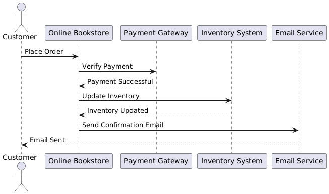
Problem Statement: A customer places an order on an online bookstore. The system needs to verify the payment, update the inventory, and send a confirmation email to the customer.
Sequence Diagram:
Interpretation:
- The customer places an order on the online bookstore.
- The online bookstore verifies the payment with the payment gateway.
- The payment gateway confirms the payment is successful.
- The online bookstore updates the inventory system.
- The inventory system confirms the update.
- The online bookstore sends a confirmation email to the customer via the email service.
- The email service confirms that the email has been sent to the customer.
Example 2: Library Book Return
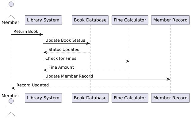
Problem Statement: A library member returns a book. The system needs to update the book’s status, check for any fines, and update the member’s record.
Sequence Diagram:
Interpretation:
- The member returns a book to the library system.
- The library system updates the book’s status in the book database.
- The book database confirms the status update.
- The library system checks for any fines using the fine calculator.
- The fine calculator returns the fine amount (if any).
- The library system updates the member’s record.
- The member’s record confirms the update to the member.
Example 3: E-commerce Product Search
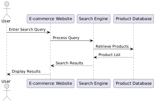
Problem Statement: A user searches for a product on an e-commerce website. The system needs to retrieve and display the search results.
Sequence Diagram:
Interpretation:
- The user enters a search query on the e-commerce website.
- The e-commerce website processes the query using the search engine.
- The search engine retrieves the relevant products from the product database.
- The product database returns the list of products to the search engine.
- The search engine sends the search results to the e-commerce website.
- The e-commerce website displays the search results to the user.
Example 4: Bank ATM Withdrawal
Problem Statement: A customer uses an ATM to withdraw cash. The system needs to verify the PIN, check the account balance, and dispense the cash.
Sequence Diagram:
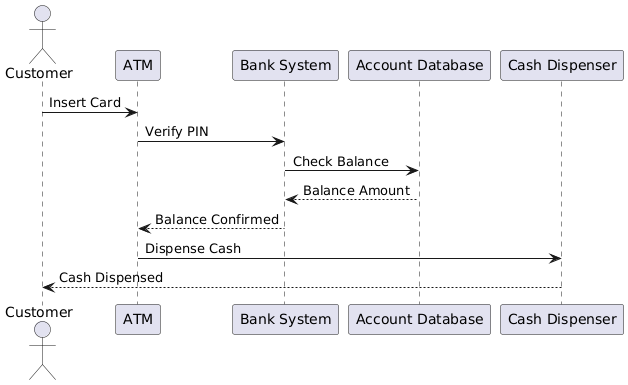
Interpretation:
- The customer inserts their card into the ATM.
- The ATM verifies the PIN with the bank system.
- The bank system checks the account balance in the account database.
- The account database returns the balance amount to the bank system.
- The bank system confirms the balance to the ATM.
- The ATM instructs the cash dispenser to dispense the cash.
- The cash dispenser dispenses the cash to the customer.
Example 5: Restaurant Order Management
Problem Statement: A customer places an order at a restaurant. The system needs to send the order to the kitchen, update the order status, and notify the waiter when the order is ready.
Sequence Diagram:
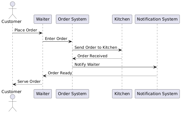
Interpretation:
- The customer places an order with the waiter.
- The waiter enters the order into the order system.
- The order system sends the order to the kitchen.
- The kitchen confirms receipt of the order.
- The order system notifies the waiter via the notification system when the order is ready.
- The notification system informs the waiter that the order is ready.
- The waiter serves the order to the customer.
These examples illustrate how sequence diagrams can be used to model various scenarios in different domains, providing a clear visualization of the interactions between different components of a system.
11. Conclusion
11.1 Summary of Key Points
In summary, sequence diagrams are a powerful tool for modeling the dynamic behaviors of a system. They provide a visual representation of how objects interact over time, making them essential for designing, documenting, and communicating system behavior.
11.2 Implications for Software Engineering
The implications of sequence diagrams for software engineering are significant. They help in understanding the flow of control and data between different components, ensuring that the system meets the specified requirements. By integrating sequence diagrams with other UML diagrams and development methodologies, developers can create comprehensive and coherent models of complex systems.
11.3 Final Thoughts
Sequence diagrams are a vital component of UML modeling, providing a visual representation of the dynamic behaviors of a system. By following best practices, using advanced features, and integrating with other tools and methodologies, developers can effectively model and design complex systems using sequence diagrams.
References
- What is Sequence Diagram? – Visual Paradigm
- Sequence Diagram – UML Diagrams – Unified Modeling Language Tool – Visual Paradigm
- Creating Sequence Diagrams in UML: A Comprehensive Tutorial – Visual Paradigm Guides
- Sequence Diagram Tutorial – Visual Paradigm
- Understanding Sequence Diagram Notation in UML – Visual Paradigm Guides
- Sequence Diagram – Visual Paradigm
- Online Sequence Diagram Tool – Visual Paradigm
- Sequence Diagram, UML Diagrams Example: Object Creation and Deletion – Visual Paradigm Community Circle
- Sequence Diagram Templates – Visual Paradigm
- Modeling Looping and Iteration Logic Using UML Sequence Diagrams – Cybermedian
These references provide a comprehensive overview of sequence diagrams and their application in UML, covering various aspects from basic concepts to advanced techniques and tools.

