Introduction
An Object Diagram in the Unified Modeling Language (UML) is a type of static structure diagram that shows a snapshot of the detailed state of a system at a particular moment in time. It is similar to a Class Diagram but focuses on instances of classes (objects) and their relationships.
Key Concepts
- Objects: Represented as rectangles, similar to classes, but with underlined names to indicate instances.
- Links: Connections between objects, representing relationships.
- Attributes: Specific values for the attributes of the objects.
- Associations: Lines connecting objects, showing how they are related.
Components in the Object Diagram

1. Objects and Classes
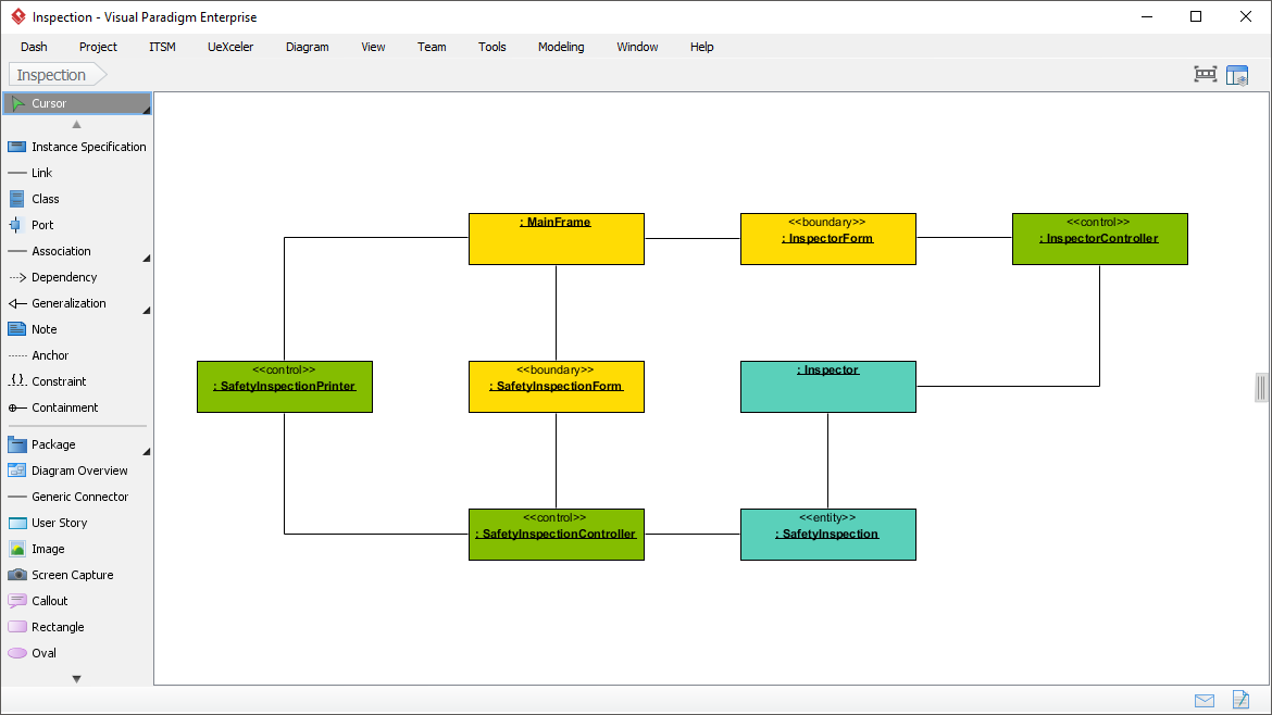
- MainFrame: This is the central object in the diagram. It likely represents the main window or frame of an application.
- InspectorForm: This object is associated with the
MainFrameand is labeled with a stereotype«boundary», indicating it is part of the user interface. - InspectorController: This object is associated with
InspectorFormand is labeled with a stereotype«control», indicating it handles the logic for the inspector functionality. - SafetyInspectionForm: Another boundary object associated with
MainFrame, likely representing a form for safety inspections. - SafetyInspectionPrinter: This object is associated with
SafetyInspectionFormand is labeled with a stereotype«control», indicating it handles printing logic for safety inspections. - SafetyInspection: This object is labeled with a stereotype
«entity», indicating it represents data or a business entity related to safety inspections. - SafetyInspectionController: This object is associated with
SafetyInspectionand is labeled with a stereotype«control», indicating it handles the logic for safety inspections.
2. Relationships
- Associations: The lines connecting the objects represent associations. For example,
MainFrameis associated withInspectorFormandSafetyInspectionForm. - Dependencies: The arrows indicate dependencies between objects. For example,
InspectorFormdepends onInspectorController.
3. Stereotypes
- «boundary»: Indicates objects that are part of the user interface.
- «control»: Indicates objects that handle the logic or control flow.
- «entity»: Indicates objects that represent data or business entities.
Steps to Create an Object Diagram
- Identify Objects: Determine the key objects in your system that you want to model. These are instances of classes.
- Define Attributes: Specify the attributes of each object and their values at a particular moment.
- Establish Links: Draw lines to show relationships between objects. Use arrows to indicate dependencies or directional associations.
- Add Stereotypes: Use stereotypes to categorize objects (e.g.,
«boundary»,«control»,«entity»). - Label Associations: Clearly label the associations to indicate the nature of the relationship.
Example Analysis of the Attached Diagram
- MainFrame: The central object that likely represents the main window of the application.
- InspectorForm: A boundary object associated with
MainFrame, representing a form for inspection. - InspectorController: A control object that handles the logic for
InspectorForm. - SafetyInspectionForm: Another boundary object associated with
MainFrame, representing a form for safety inspections. - SafetyInspectionPrinter: A control object that handles printing logic for
SafetyInspectionForm. - SafetyInspection: An entity object representing data related to safety inspections.
- SafetyInspectionController: A control object that handles the logic for
SafetyInspection.
Conclusion
An Object Diagram provides a detailed view of the system’s state at a specific time, showing the instances of classes and their relationships. It is useful for understanding the runtime structure of a system and how objects interact with each other. The attached diagram illustrates a typical setup for an inspection system, with clear distinctions between boundary, control, and entity objects.
References
- What is Object Diagram?
- URL: https://www.visual-paradigm.com/guide/uml-unified-modeling-language/what-is-object-diagram/
- This guide provides a comprehensive overview of UML Object Diagrams, explaining their purpose and how they differ from Class Diagrams. It also includes practical examples and tips for creating Object Diagrams using Visual Paradigm1.
- Object Diagram in UML: Bridging the Gap Between Classes and Instances – Visual Paradigm Guides
- URL: https://guides.visual-paradigm.com/object-diagram-in-uml-bridging-the-gap-between-classes-and-instances/
- This article discusses the role of Object Diagrams in UML, their relationship with Class Diagrams, and how they are used in the software development process. It includes a case study to illustrate the concepts2.
- How to Draw Object Diagram?
- URL: https://www.visual-paradigm.com/support/documents/vpuserguide/94/2584/7191_drawingobjec.html
- A step-by-step guide on creating UML Object Diagrams using Visual Paradigm. It covers the basics of Object Diagrams and provides detailed instructions on how to draw them3.
- Object Diagram – UML 2 Diagrams – UML Modeling Tool
- URL: https://www.visual-paradigm.com/VPGallery/diagrams/Object.html
- This resource offers an overview of Object Diagrams in UML 2, explaining their purpose and how they fit into the broader UML framework. It includes examples and tips for creating effective Object Diagrams4.
- Class diagrams vs Object diagrams in UML – Visual Paradigm Guides
- URL: https://guides.visual-paradigm.com/class-diagrams-vs-object-diagrams-in-uml/
- This guide compares Class Diagrams and Object Diagrams in UML, explaining their differences and when to use each type. It provides insights into how these diagrams complement each other in software modeling5.
These references should provide a solid foundation for understanding and creating UML Object Diagrams.

