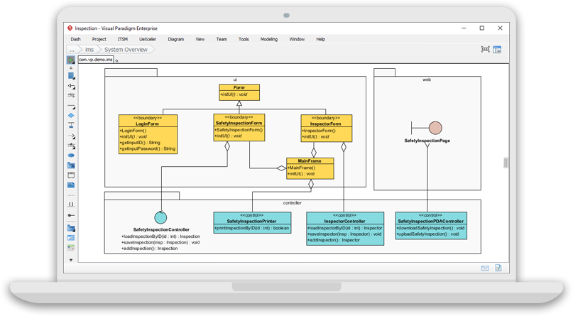
Unified Modeling Language (UML) is a standardized modeling language used to visualize the design of a system. It provides a way to create blueprints for software systems, illustrating various aspects such as system structure, behavior, and interactions. This guide will cover the essential types of UML diagrams, their purposes, and how to create them effectively.
Introduction to UML
UML is a graphical language for visualizing, specifying, constructing, and documenting the artifacts of a software-intensive system. It was developed to provide a standard way to create and share software designs. UML includes a set of integrated diagrams that can be used to model different aspects of a system.

Types of UML Diagrams
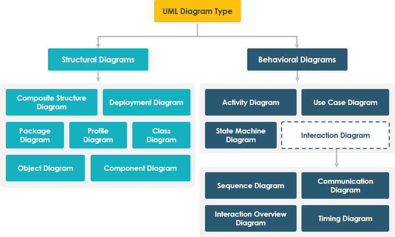
UML diagrams are categorized into two main types: structural diagrams and behavioral diagrams.

Structural Diagrams
Structural diagrams represent the static aspects of a system, focusing on the things that must be present in the system being modeled.
- Class Diagram
- Purpose: Shows the static structure of a system, including classes, attributes, methods, and the relationships between them.
- Components: Classes, attributes, methods, associations, aggregations, compositions, and inheritance.
- Usage: Used for detailed modeling of the system’s structure, identifying key components and their interactions.
- Object Diagram
- Purpose: Represents a snapshot of the detailed state of a system at a particular moment in time.
- Components: Objects and their links, which are instances of classes and associations in a class diagram.
- Usage: Used to illustrate examples of system structure at a specific point in time.
- Component Diagram
- Purpose: Describes how the physical components of a system are organized and interact with each other.
- Components: Components, interfaces, ports, and connectors.
- Usage: Used to model the physical aspects of a system, such as executables, libraries, and files.
- Deployment Diagram
- Purpose: Shows the configuration of run-time processing nodes and the components that live on them.
- Components: Nodes, artifacts, and communication paths.
- Usage: Used to model the physical deployment of artifacts on nodes, illustrating the system’s hardware topology.
- Package Diagram
- Purpose: Organizes the elements of a model into groups, called packages, to provide a better structure and manageability.
- Components: Packages and their dependencies.
- Usage: Used to organize and manage large systems by grouping related elements together.
- Composite Structure Diagram
- Purpose: Shows the internal structure of a classifier, including its interactions with the environment through ports.
- Components: Parts, ports, connectors, and collaborations.
- Usage: Used to model the internal structure of a class, including its interactions with other parts.
Behavioral Diagrams
Behavioral diagrams represent the dynamic aspects of a system, focusing on what must happen in the system being modeled.
- Use Case Diagram
- Purpose: Describes the functionality provided by a system in terms of actors and use cases.
- Components: Actors, use cases, and relationships between them.
- Usage: Used to capture the functional requirements of a system from the user’s perspective.
- Sequence Diagram
- Purpose: Shows how objects interact in a particular scenario of a use case, focusing on the sequence of messages exchanged.
- Components: Objects, lifelines, messages, and activation bars.
- Usage: Used to model the interaction between objects in a specific scenario, illustrating the sequence of events.
- Communication Diagram
- Purpose: Emphasizes the relationships between objects and the messages that pass between them.
- Components: Objects, links, and messages.
- Usage: Used to model the interaction between objects, focusing on the structure of the interactions.
- State Machine Diagram
- Purpose: Describes the states of an object and the transitions between those states in response to events.
- Components: States, transitions, events, and actions.
- Usage: Used to model the behavior of an object throughout its lifecycle, illustrating the different states and transitions.
- Activity Diagram
- Purpose: Models the workflow of a system, showing the sequence of activities and the flow of control from one activity to another.
- Components: Activities, actions, control flows, object flows, and swimlanes.
- Usage: Used to model the dynamic aspects of a system, focusing on the flow of control and data.
- Interaction Overview Diagram
- Purpose: Provides a high-level view of the interactions in a system, showing the sequence of interactions and their relationships.
- Components: Interaction overview frames, interaction occurrences, and sequence diagrams.
- Usage: Used to provide an overview of the interactions in a system, illustrating the sequence and relationships between different interactions.
- Timing Diagram
- Purpose: Shows the interactions between objects over time, focusing on the timing constraints and the duration of interactions.
- Components: Lifelines, duration constraints, time constraints, and state timelines.
- Usage: Used to model the timing aspects of a system, illustrating the interactions between objects over time.
Creating UML Diagrams
Creating UML diagrams involves several steps, from identifying the requirements to designing and refining the diagrams. Here are the general steps to create UML diagrams:
- Identify Requirements: Understand the system’s requirements and the aspects that need to be modeled.
- Choose the Appropriate Diagram: Select the type of UML diagram that best fits the aspect of the system you want to model.
- Define the Components: Identify the key components, such as classes, objects, actors, and use cases, that will be included in the diagram.
- Draw the Diagram: Use a UML modeling tool to create the diagram, placing the components and defining their relationships.
- Refine the Diagram: Review and refine the diagram to ensure accuracy and completeness.
- Validate the Diagram: Validate the diagram with stakeholders to ensure it meets the requirements and accurately represents the system.
Tools for Creating UML Diagrams
Several tools are available for creating UML diagrams, ranging from simple drawing tools to comprehensive modeling environments. Some popular UML tools include:
- Visual Paradigm: A comprehensive modeling tool that supports all types of UML diagrams and provides a user-friendly interface for creating and managing diagrams.
- Microsoft Visio: A powerful diagramming tool that supports UML diagrams and integrates with other Microsoft Office applications.
- StarUML: A software modeling tool that supports UML and other modeling languages, providing a range of features for creating and managing diagrams.
- Draw.io: A free online diagramming tool that supports UML diagrams and offers a user-friendly interface for creating and sharing diagrams.
Conclusion
UML diagrams are essential tools for visualizing and communicating the design of a system. By understanding the different types of UML diagrams and their purposes, you can effectively model the structure and behavior of a system, ensuring that all aspects are accurately represented. Whether you are a software developer, architect, or analyst, mastering UML diagrams will enhance your ability to design and communicate complex systems effectively.
References
- UML Class Diagram Tutorial
- This tutorial provides a comprehensive guide to UML class diagrams, covering everything from the basics to advanced concepts. It includes detailed explanations and examples to help you understand and create class diagrams effectively10.
- What is Unified Modeling Language (UML)?
- This article introduces the Unified Modeling Language (UML), explaining its purpose, history, and the 13 different types of UML diagrams. It includes detailed descriptions and examples of each diagram type to help you understand their usages11.
- Overview of the 14 UML Diagram Types
- This overview provides a quick introduction to the 14 UML diagram types, helping you understand the different aspects of UML and how to start learning it. It includes a UML map for easy navigation and a learning plan to guide your UML journey12.
- What is Class Diagram?
- This guide explains what a UML class diagram is, its components, and how to create one. It covers the structure of a system, including classes, attributes, operations, and relationships, with clear examples and tips13.
- UML Practical Guide – All you need to know about UML modeling
- This practical guide covers all aspects of UML modeling, from basic concepts to advanced techniques. It includes detailed explanations of different UML diagrams, their purposes, and how to use them effectively in software development14.
- Online UML Diagram Tool
- This online UML diagram tool allows you to create UML diagrams quickly and easily. It features a fast and intuitive web UML editor with powerful diagramming tools and on-the-fly UML syntax checks15.
- What is Sequence Diagram?
- This guide explains what a UML sequence diagram is, its components, and how to create one. It covers the dynamic behavior of a system, including objects, lifelines, messages, and interactions, with clear examples and tips16.
- Modeling Looping and Iteration Logic Using UML Sequence Diagrams – Cybermedian
- This article discusses how to model looping and iteration logic using UML sequence diagrams. It provides insights into representing complex interactions and includes examples to illustrate the concepts17.
- UML Diagrams: A Comprehensive Guide – Cybermedian
- This comprehensive guide covers the three main types of UML diagrams: Structural Diagrams, Behavioral Diagrams, and Interaction Diagrams. It explains their purposes, components, and how to use them in software engineering18.
- Free UML Tool
- This free online UML tool allows you to create UML diagrams easily with a simple and intuitive editor. It features no ads, no limitations on the number of shapes or diagrams, and various formatting options to enhance your diagrams19.
