Class diagrams are a fundamental part of Unified Modeling Language (UML), providing a structural view of a system by illustrating classes, interfaces, collaborations, and their relationships. This guide will cover the key concepts, components, and uses of class diagrams, helping you understand and effectively utilize them in system modeling.
Purpose of Class Diagrams
A class diagram is a structural diagram that shows a set of classes, interfaces, and collaborations, and their relationships. It is the most common diagram in modeling object-oriented systems. Class diagrams address the static design view of a system, modeling the vocabulary of a system, collaborations, or schemas. They serve as the foundation for component and deployment diagrams.
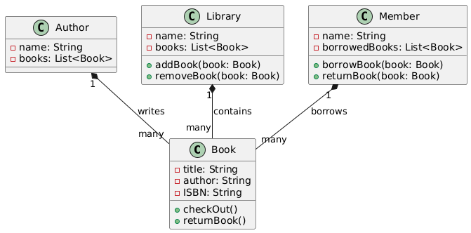
Example: In a library management system, a class diagram might show classes like Book, Author, Library, and Member, along with their relationships and attributes.
Static View
Class diagrams represent the static view of a system, meaning they do not show time-dependent behavior. They depict the elements of a model independent of time. These diagrams show the meaningful and useful concepts that may exist in the real world, in software or hardware implementations, or only in the abstract. They may include elements that represent real-world concepts, abstract concepts, implementation concepts, or computer concepts.
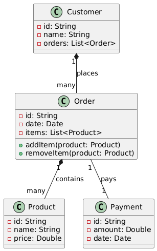
Example: In an e-commerce system, a class diagram might include classes like Product, Customer, Order, and Payment, showing their attributes and relationships without considering the sequence of operations.
Classes
Definition and Characteristics
A class is a description of a set of objects that share the same attributes, operations, relationships, and semantics. It is an abstraction of things that are part of a system’s vocabulary. Classes are the most common UML modeling element. The other modeling elements describe some behavior, internal structure, arrangement, relationships, or organization of one or more classes.
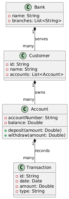
Example: In a banking system, a class diagram might include classes like Account, Customer, Transaction, and Bank, each with its own set of attributes and operations.
Types of Classes
- Software Classes: Represent software entities.
- Hardware Classes: Represent hardware components.
- Conceptual Classes: Represent abstract concepts.
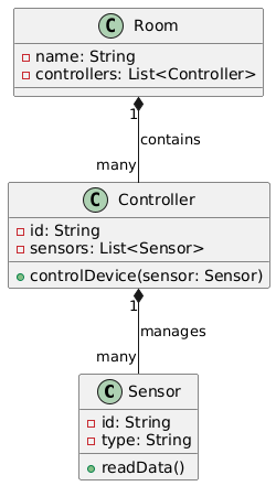
Example: In a smart home system, classes might include Sensor (hardware), Controller (software), and Room (conceptual).
Components of a Class
- Attributes: Properties of the class in which we are interested.
- Operations: Things that objects of that class can do.
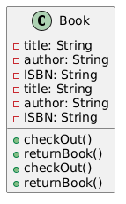
Example: A Book class might have attributes like title, author, and ISBN, and operations like checkOut() and returnBook().
Notation
The notation for a class is a rectangle with a mandatory compartment for the name. An optional compartment can show the attributes of the class. A class may have an optional compartment to show the operations of the class.
Example:
Levels of Abstraction
Classes can exist at different levels of meaning, including analysis, design, and implementation levels.
Example: In a software development project, you might have an analysis-level class like User, a design-level class like UserInterface, and an implementation-level class like UserLoginForm.
Abstract and Concrete Classes
- Abstract Class: A class that cannot be directly instantiated. Its name may be in italics.
- Concrete Class: A class that can have individual instances.
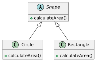
Example: An abstract class Shape with subclasses Circle and Rectangle.
Class-Scope Attributes and Operations
A class can be regarded as a global object. Class-scope attributes are attributes of this implicit object. A class-scope operation applies to the class itself, not to an object.
Example: A MathUtility class with a class-scope operation factorial(int n).
Stereotypes
A class can be shown with a stereotype using guillemets (« and »). Stereotypes indicate a special category of model element or a new term in the grammar. A class may have a creation operation (constructor), which is shown as an underlined operation in the class.
Example:

Relationships
Class diagrams also show relationships among classes. These relationships include:
Associations
Associations describe semantic connections among individual objects of given classes. They provide the connections with which objects of different classes can interact.
Example: A Customer class associated with an Order class, indicating that a customer can place orders.
Generalization
Generalization relates general descriptions of parent classifiers (superclasses) to more specialized child classifiers (subclasses). It facilitates the description of classifiers using incremental declarations that add to the description inherited from ancestors.
Example: A Vehicle class with subclasses Car and Bicycle.
Dependencies
Dependencies show relationships among elements, such as levels of abstraction, template parameters, permissions, or usage.
Example: A Logger class that depends on a FileWriter class to write log files.
Instances and Objects
Definition
An object is an instance of a class. It is an individual with identity whose structure and behavior are described by the class. Objects have state, which is the current values of their attributes.
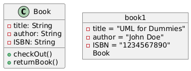
Example: An instance of the Book class with the title “UML for Dummies”.
Notation
The notation for a UML instance specification (object) is a box with a mandatory compartment for the name field, which includes an object name, a “:”, and the name of the instantiated class. An optional second compartment can show the slots, i.e., the attributes and their current values. The name of the instance is underlined.
Example:
Appearance in Diagrams
Instances can appear on both class and object diagrams. A class can be connected to its instance with a dashed arrow indicating a dependency. Class diagrams can include instances to visualize the (possibly dynamic) type of an instance.
Example: A class diagram showing a Library class with an instance mainLibrary connected by a dashed arrow.
Diagram Contents
Class diagrams contain classes, interfaces, collaborations, and relationships. They may also contain notes and constraints. Class diagrams can include packages or subsystems to group model elements into larger chunks.
Example: A class diagram for a university system might include packages like StudentManagement, CourseManagement, and FacultyManagement.
Use of Class Diagrams
Class diagrams are used to model the static design view of a system. They can be used to model the vocabulary of the system, model collaborations of classes, and model logical database schemas.
Example: Using a class diagram to model the database schema for an online store, including classes like Product, Category, and Customer.
Relationship to Other Diagrams
Class diagrams are related to other diagrams, such as:
Object Diagrams
Object diagrams show instances of classes and their relationships.
Example: An object diagram showing instances of Customer and Order classes and their relationships.
Component Diagrams and Deployment Diagrams
Component diagrams and deployment diagrams are similar to class diagrams, but they contain components and nodes, respectively.
Example: A component diagram showing the software components of an e-commerce system and a deployment diagram showing how these components are deployed on servers.
Abstraction
Class diagrams are a form of abstraction that provides a simplified view of a system, capturing essential details while hiding unnecessary complexity.
Example: A high-level class diagram for a banking system that shows only the main classes and their relationships, hiding the details of individual attributes and operations.
Multiple Diagrams
Multiple class diagrams are often required to show an entire static view of a system. Each diagram should focus on a specific aspect of the system.
Example: One class diagram for the user management aspect of a system and another for the order processing aspect.
Diagram as a Projection
A class diagram is a projection into a model. It is a graphical presentation of a set of elements.
Example: A class diagram showing the projection of a subset of classes related to inventory management in a retail system.
Forward and Reverse Engineering
Class diagrams can be used for forward and reverse engineering of models and code.
Example: Using a class diagram to generate Java code for a set of classes and then using reverse engineering to update the class diagram based on changes in the code.
Metamodel
The abstract syntax of UML uses MOF models to show the UML grammar. These MOF models use a subset of UML structural diagrams. The boxes on the abstract syntax diagrams are «Metaclasses». The elements of UML are instances of these «Metaclasses».
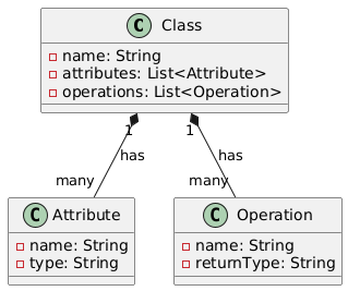
Example: A metamodel showing the abstract syntax of UML class diagrams, with «Metaclasses» like Class, Attribute, and Operation.
These concepts are fundamental to understanding and effectively utilizing class diagrams in UML for system modeling. By mastering these elements, you can create comprehensive and accurate class diagrams that effectively communicate the structure and relationships within your system.
Example 1: Library Management System
Class Diagram:
Example 2: E-commerce System
Class Diagram:
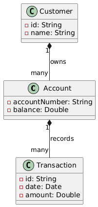
Example 3: Banking System
Class Diagram:
Example 4: Smart Home System
Class Diagram:
Example 5: Abstract and Concrete Classes
Class Diagram:
Example 6: Metamodel
Class Diagram:
Example 7: High-Level Class Diagram for Banking System
Class Diagram:
Conclusion
Class diagrams are an essential tool in Unified Modeling Language (UML), providing a clear and structured view of a system’s components and their relationships. By understanding and effectively utilizing class diagrams, developers and architects can model the static design view of a system, capture the vocabulary and collaborations of classes, and design logical database schemas.
Throughout this guide, we have explored the key concepts, components, and uses of class diagrams. We have seen how classes, attributes, operations, and relationships can be represented to model real-world, abstract, and implementation concepts. The use of stereotypes, generalization, associations, and dependencies further enriches the modeling capabilities, allowing for a comprehensive and detailed representation of a system’s structure.
The examples provided, along with their corresponding class diagrams, illustrate the practical application of class diagrams in various domains, from library management systems to e-commerce platforms and banking systems. These examples demonstrate how class diagrams can be used to model complex systems, capture essential details, and communicate the design effectively to stakeholders.
Moreover, class diagrams are not isolated entities; they are interconnected with other UML diagrams, such as object diagrams, component diagrams, and deployment diagrams. This interconnectivity allows for a holistic view of the system, ensuring that all aspects are modeled and understood.
In summary, class diagrams are a powerful and versatile tool in UML, essential for modeling the static structure of a system. By mastering the concepts and techniques discussed in this guide, you can create accurate and effective class diagrams that serve as a foundation for system design and development. Whether you are designing a new system, documenting an existing one, or communicating design ideas to stakeholders, class diagrams provide the clarity and detail needed to ensure successful outcomes.
References
- UML Class Diagram Tutorial
- UML Class Diagram Tutorial
- This comprehensive guide provides an in-depth look at UML class diagrams, including how to create and use them effectively. It also highlights the features of Visual Paradigm Community Edition, a free UML software.
- Free Class Diagram Tool
- Free Class Diagram Tool
- Visual Paradigm Online offers a free edition for creating class diagrams and other UML diagrams. This tool is user-friendly and supports various diagram types without limitations on the number of diagrams or shapes.
- What is Class Diagram?
- What is Class Diagram?
- This article explains the basics of class diagrams in UML, including their structure and components. It also provides insights into using Visual Paradigm for creating these diagrams.
- How to Draw Class Diagram?
- How to Draw Class Diagram?
- A step-by-step guide on drawing class diagrams using Visual Paradigm, including tips on creating enumerations and connecting members.
- Online Class Diagram Software
- Online Class Diagram Software
- Visual Paradigm’s online class diagram tool is designed to be fast and intuitive, allowing users to create professional UML diagrams quickly and collaboratively.
- UML Diagrams: A Comprehensive Guide
- UML Diagrams: A Comprehensive Guide
- This guide covers various types of UML diagrams, including class diagrams, and their importance in software engineering. It discusses how class diagrams depict the static structure of a system and the relationships between classes.
- A Comprehensive Guide to UML Class Diagram
- A Comprehensive Guide to UML Class Diagram
- This article provides a detailed overview of UML class diagrams, their components, and how they are used in different phases of system design. It also mentions the use of Visual Paradigm for creating these diagrams.
- Introduction to UML Diagrams in Visual Paradigm
- Introduction to UML Diagrams in Visual Paradigm
- This article introduces the various types of UML diagrams supported by Visual Paradigm, with a focus on class diagrams and their role in modeling the static structure of a system.
- Learning Class Diagrams with Visual Paradigm
- Learning Class Diagrams with Visual Paradigm
- A step-by-step guide on creating class diagrams using Visual Paradigm, including best practices for keeping the diagrams simple and clear.
- Navigating UML: An Overview of the 14 Diagram Types and Their Relevance in Agile Environments
- Navigating UML: An Overview of the 14 Diagram Types and Their Relevance in Agile Environments
- This overview discusses the different types of UML diagrams, including class diagrams, and their relevance in agile software development environments.
These references provide a comprehensive understanding of class diagrams and UML, along with practical guides on using Visual Paradigm for creating these diagrams.

