Use case diagrams are a crucial component of Unified Modeling Language (UML), providing a visual representation of the interactions between users (actors) and a system. This guide will cover the key concepts, components, and uses of use case diagrams, helping you understand and effectively utilize them in system modeling.

Purpose of Use Case Diagrams
Use case diagrams are used to model the behavior of a system, subsystem, or class, showing the outwardly visible services that the system provides in the context of its environment. They capture the functional requirements of a system, helping in understanding how users interact with a system and what they expect from it. Use case diagrams represent the functionality of a subject (such as a system), as perceived by outside agents called actors, that interact with the subject from a particular viewpoint.
Use Cases
Definition and Characteristics
A use case represents a unit of functionality or a goal that a user (actor) wants to achieve with the system. It describes a sequence of actions that a system performs to yield an observable result of value to an actor. Key characteristics include:
- Goal-Oriented: Each use case represents a purpose or goal that some user wants the system to help achieve.
- Operation: A use case can be considered an operation invoked by an outside user.
- Behavioral Model: Use cases are part of the behavioral model of the system and are often considered as operations on the system.
- Scenarios: A use case can be a description of a set of sequences, where each sequence represents one possible flow through all variations. Each sequence is called a scenario.
- Classifier: A use case is a classifier, so it may have attributes and operations, similar to classes.
Example
In an e-commerce system, a use case might be “Place Order,” which describes the sequence of actions a customer performs to place an order, including adding items to the cart, entering payment information, and confirming the order.
Actors
Definition and Characteristics
An actor represents a user or an external entity (such as another system) that interacts with the system. Actors initiate use cases. Key characteristics include:
- External Entities: Actors are not part of the system itself.
- Roles: Actors represent roles, not specific individuals or business titles.
- Generalization: Actors can be generalized or specialized. When an actor is specialized, all the specialized actors can participate in the same use cases as the general actor.
- Types: Actors can be humans, other computer systems, or processes.
Example
In a library management system, actors might include “Librarian,” “Member,” and “External System” (e.g., a book supplier).
Subject
A subject is a classifier that offers the use cases to the actors. It is usually the system or a subsystem. A use case can have many subjects. A subject is shown as a box with the name and optional stereotype in the upper left.
Example
In a banking system, the subject might be “Banking System,” which offers use cases like “Withdraw Money,” “Deposit Money,” and “Transfer Funds” to actors like “Customer” and “Bank Teller.”
Relationships
Use cases and actors are connected by relationships, including:
Associations
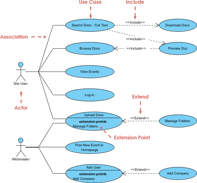
Associations indicate communication paths between actors and use cases. An association between an actor and a use case shows that they communicate with one another.
Generalization
Generalization shows a relationship between a general use case and a more specific use case. It is drawn as a solid line with a triangular arrowhead, similar to class generalization.
Include
Include is used to extract common behavior that is shared between multiple use cases into a separate use case. An include relationship is shown by a dashed arrow with the keyword «include». The arrow points from the base use case to the included use case.
Extend
Extend is used to add optional or conditional behavior to a base use case. The extend relationship is shown as a dashed arrow with the keyword «extend», pointing from the extension to the base.
Example
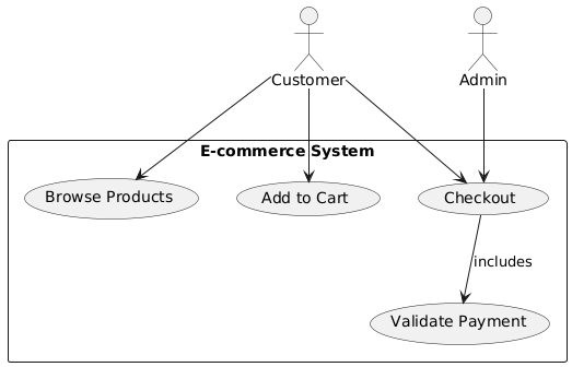
In an online shopping system, the use case “Checkout” might include the use case “Validate Payment,” and the use case “Add to Cart” might extend the use case “Browse Products.”
Notation
Use Cases
A use case is represented as an ellipse with its name inside or below it.
Actors
Actors are represented as stick figures, or as stereotyped class boxes.
Subject
A subject is usually shown as a rectangle.
Example

Diagram Header
The diagram header kind is usually ‘pkg’, but other namespace containers like ‘class’ and ‘component’ are also possible.
Simplifying Use Cases
Techniques like generalization, include, and extend can be used to simplify complex use cases.
Naming Conventions
- Verb Phrases: Use case names should be verb phrases in the present tense, indicating the goal of the actor.
- Avoid Nouns: Avoid using noun or participle forms, and avoid using completed behaviors.
- Actor Terminology: Use the terminology of the actors, avoiding jargon or implementation concepts.
- Simple Terms: Use simple, unambiguous terms that everyone can understand.
- Goal Statement: A useful trick is to precede the goal with the words “O System, please help me to…”
Example
In a project management system, a use case might be named “Create Task” instead of “Task Creation.”
Use Case Template
While there isn’t a formal “use case template” specified in the sources, the following items are often documented for a use case:
- Name: A verb phrase describing the goal the actor wants to achieve.
- Actors: The users or external entities that interact with the use case.
- Subject: The system or subsystem that provides the functionality.
- Description: A textual description of the use case.
- Flow of Events: The steps of how and when the use case starts and ends, what the use case does, how it interacts with actors, and what information is exchanged.
- Scenarios: Specific instances or variations of the use case.
- Relationships: How the use case relates to other use cases (include, extend, generalization).
- Preconditions and Postconditions: Define the state before and after the execution of a use case.
- Extension Points: Specific points in the base use case where an extension can occur.
Example
Use Case: Place Order
| Field | Description |
|---|---|
| Name | Place Order |
| Actors | Customer |
| Subject | E-commerce System |
| Description | The customer places an order by adding items to the cart, entering payment information, and confirming the order. |
| Flow of Events | 1. The customer browses products. 2. The customer adds items to the cart. 3. The customer enters payment information. 4. The customer confirms the order. 5. The system processes the payment and confirms the order. |
| Scenarios | – Successful order placement. – Payment failure. – Out of stock items. |
| Relationships | Includes “Validate Payment”, extends “Browse Products”. |
| Preconditions | The customer must be logged in. |
| Postconditions | The order is confirmed, and the payment is processed. |
Use Case Instances
A use case instance is an execution of a use case initiated by a message from an instance of an actor. A use case instance may follow other use cases related by extend or include relationships. A use case instance can have attributes and operations to represent the progress of execution and the effect on the system.
Diagram Usage
Use case diagrams are typically used during the analysis phase to capture the functional requirements of a system. They can be used to model the context of a system, or to model the requirements of the system.
Relationship to Other Diagrams
Use cases can be detailed using other UML diagrams such as sequence diagrams, state machine diagrams, or communication diagrams. Sequence diagrams, collaboration diagrams, and activity diagrams can be used to show the behavior of the use cases and the interactions of the system with actors.
Forward and Reverse Engineering
While use case diagrams don’t specify the implementation of a system and cannot be directly forward or reverse engineered, they can be used for testing by generating test scripts based on their flows of events.
Packages
Use cases are often organized into packages. It is recommended to produce use case-focused packages, where a package is constructed for each actor, and the associated use cases and classes are placed within each package. Packages can also be organized in layers based on the system’s architecture.
Example
In a healthcare system, packages might include “Patient Management,” “Appointment Scheduling,” and “Billing,” each containing relevant use cases and classes.
Conclusion
Use case diagrams are a valuable tool for modeling and understanding system behavior from the user’s perspective. By using these elements and concepts, you can create comprehensive and effective use case diagrams that serve as a foundation for system design and development. Whether you are designing a new system, documenting an existing one, or communicating design ideas to stakeholders, use case diagrams provide the clarity and detail needed to ensure successful outcomes.
References
- What is Use Case Diagram?
- This article provides an introduction to use case diagrams, explaining their purpose and key components. It includes examples to illustrate the concepts discussed20.
- Use Case Diagram Tutorial
- A comprehensive tutorial that covers the basics of use case diagrams, including how to create them and when to use them. It also provides examples and tips for effective use case diagramming21.
- Use Case Diagram Templates
- This resource offers free online use case diagram templates and examples. It allows users to create professional use case diagrams using an intuitive online diagram software22.
- Online Use Case Diagram Tool
- Visual Paradigm Online provides an easy-to-use online UML diagram maker with a rich set of customizable use case diagram examples to help users get started quickly23.
- SysML: Identify User Requirements with Use Case Diagrams
- This guide explains how to use SysML use case diagrams to identify and document user requirements. It includes examples to illustrate the concepts discussed24.
- Free Use Case Diagram Tool
- A free online use case diagram tool that supports UML, ERD, and Organization Chart. It allows users to draw use case diagrams quickly through an intuitive UML drawing editor25.
- Comprehensive Tutorial on Use Case Diagrams – Cybermedian
- This tutorial provides a detailed guide to creating and understanding use case diagrams, using the Wheels bike hire system as an example26.
- Use Case Diagram, UML Diagrams Example: Business Use Case Diagram Example – Visual Paradigm Community Circle
- This article provides an example of a business use case diagram, explaining how business use case diagrams are used to represent the functionality provided by an organization as a whole27.
- Use Case — Learn By Examples – Cybermedian
- This resource provides examples of use case diagrams, explaining how to define the relationships between use cases and the decision-making process involved in software analysis28.

