نمودار کلاس چیست؟
اینUML نمودار کلاسیک نماد گرافیکی است که برای ساخت و تجسم سیستمهای شیگرا استفاده میشود. نمودار کلاس در زبان مدلسازی یکپارچه (UML) نوعی نمودار ساختاری ایستا است که ساختار یک سیستم را با نشان دادن:
- کلاسها،
- ویژگیهای آنها (یا خواص)،
- عملیات (یا متدها)،
- و روابط بین اشیاء را توصیف میکند.
کلاس چیست؟
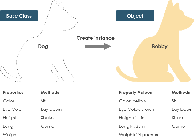
یک کلاس نقشهای برای یک شی است. اشیاء و کلاسها به هم مرتبط هستند. نمیتوانیم درباره یکی صحبت کنیم بدون اینکه درباره دیگری صحبت کنیم. و کل هدف طراحی شیگرا درباره اشیاء نیست، بلکه درباره کلاسهاست، زیرا ما از کلاسها برای ایجاد اشیاء استفاده میکنیم. بنابراین یک کلاس توصیف میکند که یک شی چه خواهد بود، اما خود شی نیست.
در واقع، کلاسها نوع اشیاء را توصیف میکنند، در حالی که اشیاء نمونههای قابل استفاده از کلاسها هستند. هر شی از همان مجموعه نقشهها ساخته شده و بنابراین شامل همان اجزاء (خواص و متدها) است. معنی استاندارد این است که یک شی نمونهای از یک کلاس است و اشیاء دارای حالتها و رفتارها هستند.
مثال
یک سگ دارای حالتها – رنگ، نام، نژاد و همچنین رفتارها – تکان دادن، پارس کردن، خوردن است. یک شی نمونهای از یک کلاس است.
نماد کلاس UML
یک کلاس نمایانگر مفهومی است که حالت (ویژگیها) و رفتار (عملیات). هر ویژگی یک نوع دارد. هرعملیاتدارای یکامضا. نام کلاستنها اطلاعات الزامی است.

نام کلاس:
- نام کلاس در بخش اول ظاهر میشود.
ویژگیهای کلاس:
- ویژگیها در بخش دوم نشان داده میشوند.
- نوع ویژگی بعد از دو نقطه نشان داده میشود.
- ویژگیها به متغیرهای عضو (اعضای داده) در کد نگاشته میشوند.
عملیات کلاس (متدها):
- عملیات در بخش سوم نشان داده میشوند. آنها خدماتی هستند که کلاس ارائه میدهد.
- نوع بازگشتی یک متد بعد از دو نقطه در انتهای امضای متد نشان داده میشود.
- نوع بازگشتی پارامترهای متد بعد از دو نقطه و پس از نام پارامتر نشان داده میشود. عملیات به متدهای کلاس در کد نگاشته میشوند.

قابلیت مشاهده کلاس
نمادهای +، – و # قبل از نام ویژگی و عملیات در یک کلاس نشاندهنده قابلیت مشاهده ویژگی و عملیات هستند.
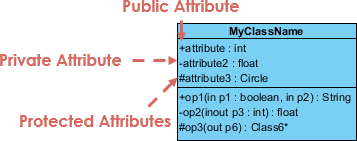
- + نشاندهنده ویژگیها یا عملیات عمومی است
- – نشاندهنده ویژگیها یا عملیات خصوصی است
- # نشاندهنده ویژگیها یا عملیات محافظتشده است
جهتگیری پارامتر
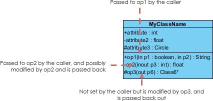
هر پارامتر در یک عملیات (متد) ممکن است به عنوان in،outیاورودی-خروجیکه جهت آن را نسبت به فراخواننده مشخص میکند. این جهتگیری قبل از نام پارامتر نشان داده میشود.
دیدگاههای نمودار کلاس
انتخاب دیدگاه بستگی به این دارد که شما در چه مرحلهای از فرآیند توسعه هستید. در حین تدوین یکمدل دامنه، به عنوان مثال، شما به ندرت ازدیدگاه مفهومی. مدلهای تحلیلیمعمولاً ترکیبی ازدیدگاههای مفهومی و مشخصاتمدل طراحیتوسعه معمولاً با تأکید زیاد بردیدگاه مشخصاتو به تدریج بهدیدگاه پیادهسازی.
یک نمودار میتواند از دیدگاههای مختلف تفسیر شود:
- مفهومی: نمایانگر مفاهیم در دامنه است
- مشخصات: تمرکز بر روی رابطهای نوع داده انتزاعی (ADT) در نرمافزار است
- پیادهسازی: توصیف میکند که چگونه کلاسها رابطهای خود را پیادهسازی خواهند کرد
دیدگاه بر میزان جزئیاتی که باید ارائه شود و انواع روابطی که ارزش ارائه دارند تأثیر میگذارد. همانطور که در بالا ذکر کردیم، نام کلاس تنها اطلاعات الزامی است.

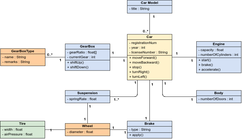
نمودار کلاس یک تکنیک مدلسازی مرکزی است که در تقریباً تمام روشهای شیگرا وجود دارد. این نمودار انواع اشیاء در سیستم و انواع مختلف روابط ایستا که بین آنها وجود دارد را توصیف میکند.
روابط
سه نوع اصلی از روابط وجود دارد که مهم هستند:
- همپیوندی — نمایانگر روابط بین نمونههای انواع (یک شخص برای یک شرکت کار میکند، یک شرکت دارای چندین دفتر است.
- وراثت — واضحترین افزوده به نمودارهای ER برای استفاده در شیگرایی است. این به وراثت در طراحی شیگرا ارتباط مستقیم دارد.
- تجمع — تجمع، نوعی از ترکیب اشیاء در طراحی شیگرا.
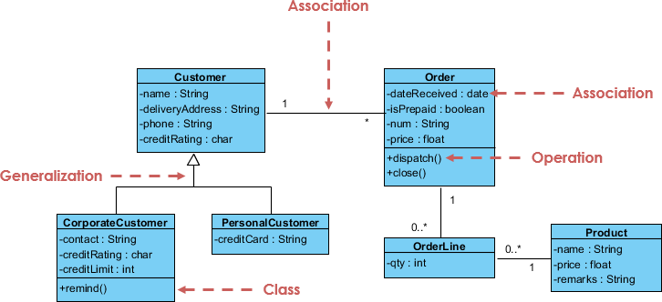
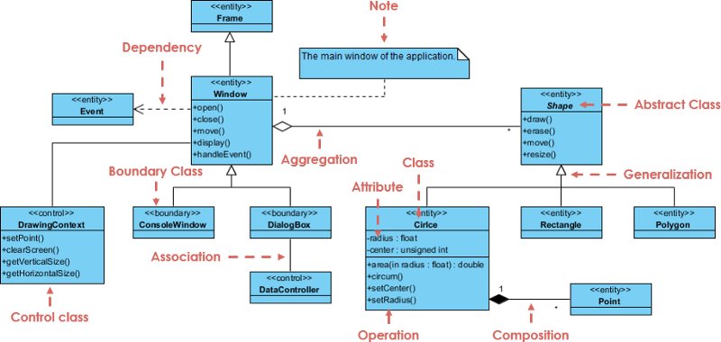
مثال نمودار کلاس: GUI
یک نمودار کلاس ممکن است یادداشتهایی به کلاسها یا روابط متصل داشته باشد.
ابزار نرمافزاری UML رایگان
در این مقاله، دو ابزار UML را معرفی میکنم:
- ویرایش جامعه Visual Paradigm (رایگان) یکابزار UML دسکتاپبا قابلیتهای مدلسازی ویژگی. (بهروزرسانی ممکن به ویرایشهای تجاری)
- Visual Paradigm Online برای UML عمومی و سایر ترسیمهای نموداری.
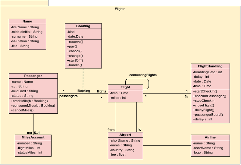
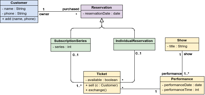
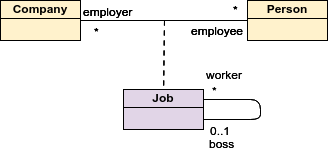
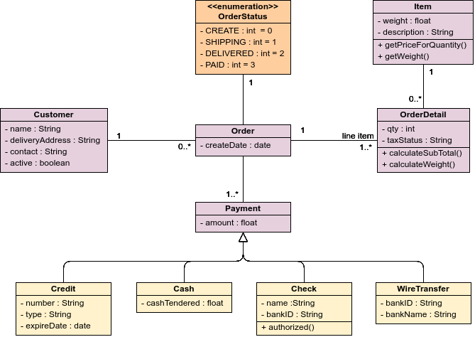
30 مثال نمودار کلاس
- مثالها و الگوهای رایگان نمودار کلاس که قابل ویرایش در نرمافزار آنلاین نمودار کلاس: Visual Paradigm Online هستند.
- از الگوها به عنوان نقطه شروع برای ایجاد نمودار کلاس خود استفاده کنید.
- (برای ویرایش فوری مثالهای نمودار کلاس کلیک کنید)
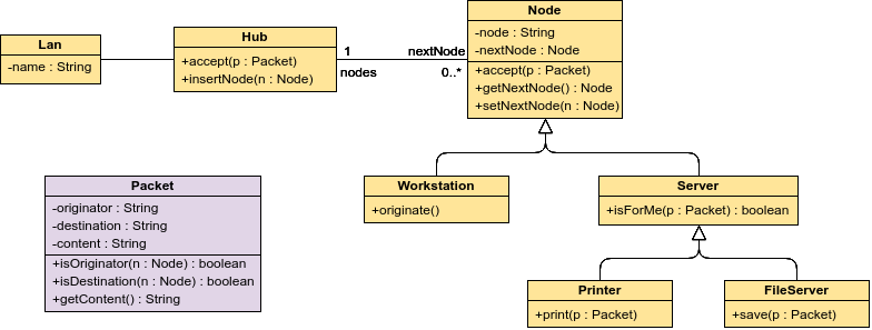
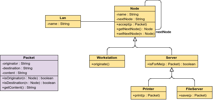
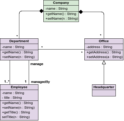
برای راحتی شما، مثالهای زیر در Visual Paradigm Online تنظیم شدهاند. شما میتوانید بلافاصله بدون پیکربندی یا نصب آن را امتحان کنید، لذت ببرید!
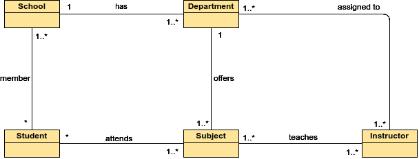
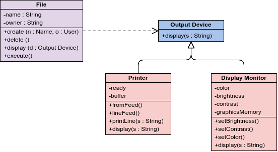
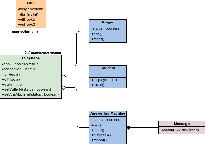
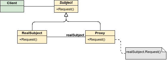

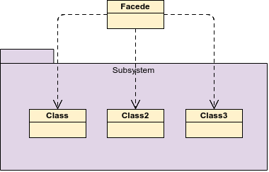
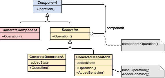
الگوهای طراحی GoF — زینتدهنده
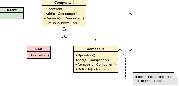
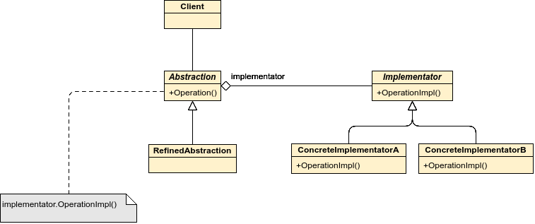
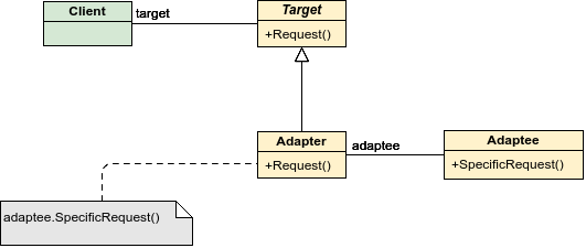

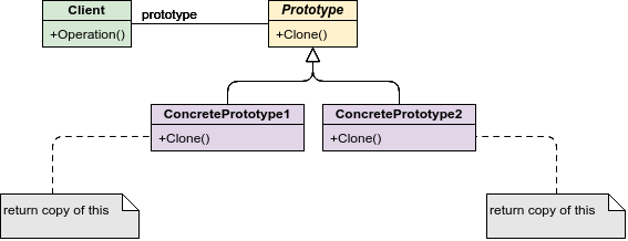
الگوهای طراحی GoF — روش کارخانه


الگوهای طراحی GoF — کارخانه انتزاعی
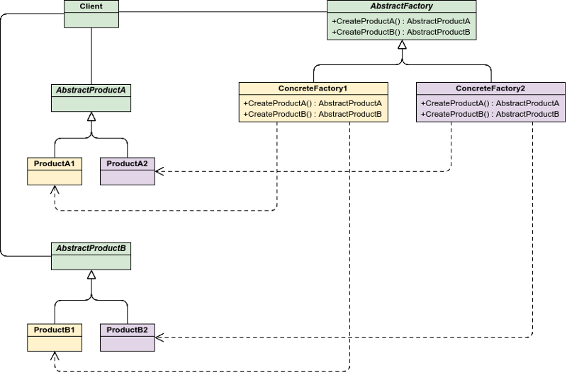
الگوهای طراحی GoF — بازدیدکننده
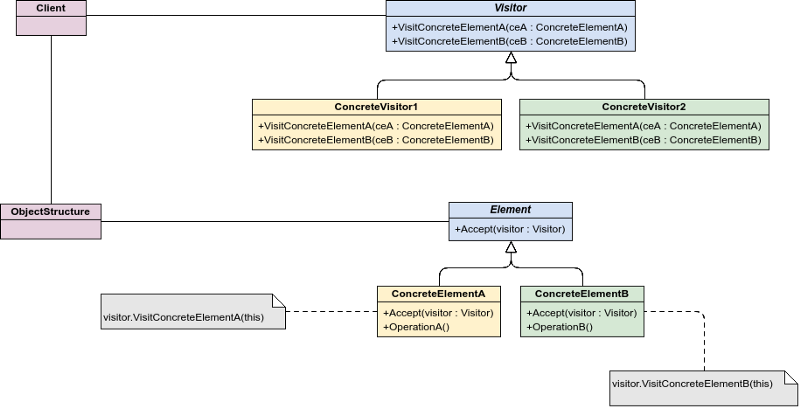
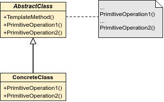


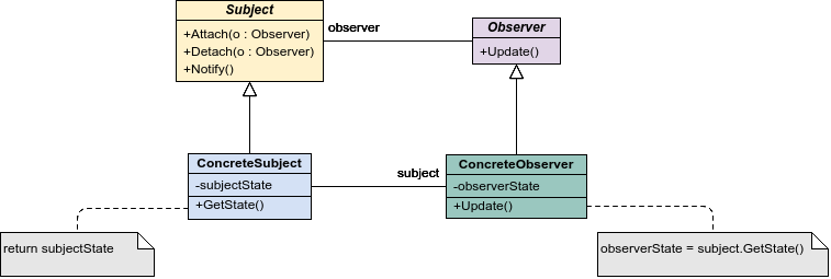


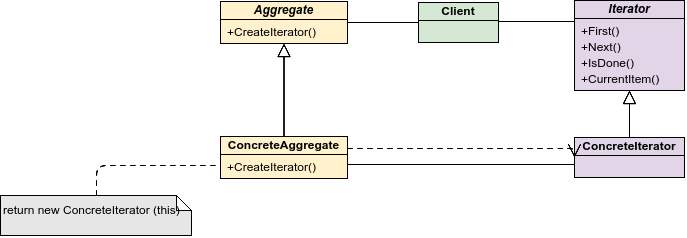
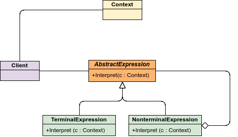
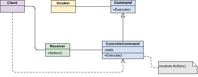
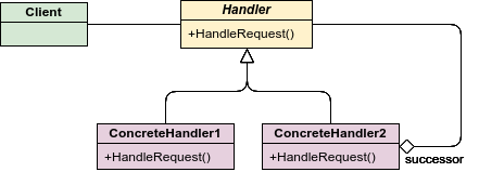
الگوهای طراحی GoF — زنجیره مسئولیت
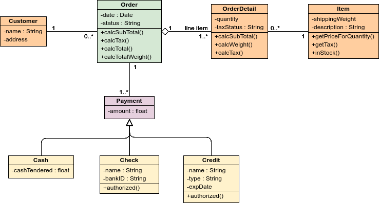
نمودار کلاس — محدودیتهای کلاسها و بستهها
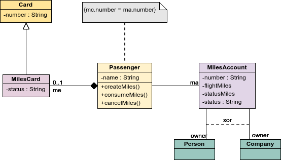
نمودار کلاس — کلاس در یک بسته (خط هوایی)

مطالعههای دیگر توصیه شده
This post is also available in Deutsch, English, Español, Français, Bahasa Indonesia, 日本語, Polski, Portuguese, Ру́сский, Việt Nam, 简体中文 and 繁體中文.


