موارد استفاده چیست؟
یک مورد استفاده یک روش شناسی است که در تحلیل سیستم برای شناسایی، روشن کردن و سازماندهی الزامات سیستم استفاده میشود.
نمودار مورد استفاده
یکنمودار مورد استفادهمدلهای مختلفی از تعامل کاربران با سیستم برای حل یک مشکل را نشان میدهد. به این ترتیب، اهداف کاربران، تعاملات بین کاربران و سیستم و رفتار مورد نیاز سیستم برای برآورده کردن این اهداف را توصیف میکند.
موارد استفادهتعاملات بین بازیگران خارجی و سیستم را برای دستیابی به اهداف خاص تعریف میکند. یک نمودار مورد استفاده شامل چهار مؤلفه اصلی است
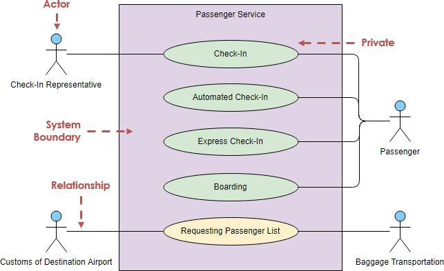
(ویرایش مثال نمودار مورد استفاده بالا)
یک نمودار مورد استفاده شامل تعدادی عنصر مدل است. مهمترین عناصر مدل عبارتند از:
بازیگر
بازیگران معمولاً افرادی هستند که با سیستم در ارتباطند و بر اساس نقشهای خود تعریف میشوند. بازیگر میتواند یک انسان یا یک سیستم خارجی دیگر باشد.
مورد استفاده
یک مورد استفاده توصیف میکند که چگونه بازیگران از یک سیستم برای دستیابی به یک هدف خاص استفاده میکنند. موارد استفاده معمولاً توسط یک کاربر برای تحقق اهدافی که فعالیتها و انواع مختلفی را در دستیابی به هدف توصیف میکنند، آغاز میشوند.
رابطه
رابطهها بین بازیگران و موارد استفاده.
مرز سیستم
مرز سیستم، سیستم مورد نظر را در ارتباط با دنیای اطراف آن تعریف میکند.
ویژگیهای مورد استفاده
یک مورد استفاده (یا مجموعهای از موارد استفاده) این ویژگیها را دارد:
- الزامات عملکردی را سازماندهی میکند
- اهداف تعاملات سیستم/بازیگر (کاربر) را مدلسازی میکند
- مسیرها را ثبت میکند (که به آنها گفته میشودسناریوها) از رویدادهای محرک به اهداف
- یک جریان اصلی از رویدادها را توصیف میکند (که به آن دوره عمل پایه نیز گفته میشود) و ممکن است جریانهای دیگری نیز وجود داشته باشد که به آنها گفته میشوداستثناییجریانهای رویداد (که به آنها دورههای عمل جایگزین نیز گفته میشود)
- چند سطحی است، به طوری که یک مورد استفاده میتواند از عملکرد مورد دیگری استفاده کند.
مورد استفاده و سناریوی مورد استفاده؟
مورد استفاده از مجموعهای از توالیهای ممکن تعاملات بین سیستمها و کاربران در یک محیط خاص و مرتبط با یک هدف خاص تشکیل شده است.
درون یک مورد استفاده چه چیزی است؟
این شامل یک گروه از عناصر (به عنوان مثال، کلاسها و رابطها) است که میتوانند به گونهای با هم استفاده شوند که تأثیری بزرگتر از مجموع عناصر جداگانه داشته باشند. مورد استفاده باید شامل تمام فعالیتهای سیستم باشد که برای کاربران اهمیت دارد.
نوع موارد استفاده
موارد استفاده اساسیدر یک فرم ایدهآل بیان میشوند که نسبتاً از جزئیات فناوری و پیادهسازی آزاد است؛ تصمیمات طراحی به تعویق میافتند و انتزاعی میشوند، به ویژه آنهایی که به رابط کاربری مربوط میشوند.
مورد استفاده عینی یا واقعی به طور عینی فرآیند را از نظر طراحی واقعی و فعلی خود توصیف میکند، متعهد به فناوریهای ورودی و خروجی خاص و غیره. هنگامی که یک رابط کاربری درگیر است، معمولاً تصاویر صفحه را نشان میدهند و درباره تعامل با ویجتها بحث میکنند.
مورد استفاده انتزاعیکامل نیست و بازیگری که آن را آغاز کند ندارد، اما توسط موارد استفاده دیگری استفاده میشود.
ساختاردهی موارد استفاده
UML سه نوع کلیشه از ارتباط بین موارد استفاده را تعریف میکند:
<<شامل>> مورد استفاده
زمان استفاده از رابطه <<شامل>> پس از اتمام توصیف اولیه از تمام موارد استفاده اصلی شما است. اکنون میتوانید به موارد استفاده نگاه کنید و توالیهای مشترک تعامل کاربر-سیستم را شناسایی کنید.

<<گسترش>> مورد استفاده
یک مورد استفاده گسترشدهنده، در واقع، یک دوره جایگزین از مورد استفاده پایه است. مورد استفاده <<گسترش>> این کار را با مفهومسازی وارد کردن توالیهای اضافی عمل به توالی مورد استفاده پایه انجام میدهد.

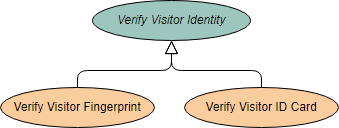
مورد استفاده انتزاعی و عمومی
مورد استفاده عمومی انتزاعی است. نمیتوان آن را نمونهسازی کرد، زیرا اطلاعات ناقصی دارد. عنوان یک مورد استفاده انتزاعی به صورت ایتالیک نمایش داده میشود.
مثال
این مثال مدلی از چندین مورد استفاده تجاری (اهداف) را نشان میدهد که تعاملات بین یک رستوران (سیستم تجاری) و بازیگران اصلی آن را نمایان میسازد.
پس از شناسایی موارد استفاده پایه در مرحله اول، شاید بتوانیم ساختاردهی بیشتری به این موارد استفاده با استفاده از موارد استفاده <<extend>> و <<include>> در مرحله دوم بهبود ببخشیم، همانطور که در شکل زیر نشان داده شده است:
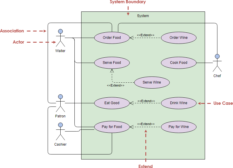
(ویرایش مثال نمودار مورد استفاده بالا)
ساختاردهی موارد استفاده با بستهها
نمودار مورد استفاده ممکن است شامل بستههایی باشد که برای ساختاردهی موارد استفاده به منظور سادهسازی تحلیل، توسعه و نگهداری یک سیستم استفاده میشوند.
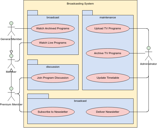
ویرایش مثال نمودار مورد استفاده بالا
مدل مورد استفاده در مقابل نمودار مورد استفاده
بخش عمدهای از مدل مورد استفاده در واقع متنی است، با متنی که در آن ثبت شده استمشخصات مورد استفادهکه با هر عنصر مدل مورد استفاده مرتبط است. این مشخصات جریان رویدادهای مورد استفاده را توصیف میکنند.
مدل مورد استفاده به عنوان یک رشته وحدتبخش در طول توسعه سیستم عمل میکند. این مدل به عنوان مشخصه اصلی الزامات عملکردی برای سیستم، به عنوان مبنایی برای تحلیل و طراحی، به عنوان ورودی برای برنامهریزی تکرار، به عنوان مبنایی برای تعریف موارد آزمایش و به عنوان مبنایی برای مستندات کاربری استفاده میشود.
مثال: توصیف مورد استفاده
- برای نوشتن محتوای یک مورد استفاده، با انتخاب یکی از سناریوها به عنوان سناریوی اصلی شروع میکنید.
- شما بدنه مورد استفاده را با نوشتن سناریوی اصلی موفقیت به عنوان یک دنباله از مراحل شمارهگذاری شده آغاز میکنید.
- سپس سناریوهای دیگر را میگیرید و آنها را به عنوان گسترشها مینویسید. گسترشها میتوانند موفقیتها باشند، مانند 3a در زیر یا شکست، مانند 6b در زیر.
- هر مورد استفاده یک بازیگر اصلی دارد که از سیستم میخواهد یک خدمت ارائه دهد.
- هر مرحله در یک مورد استفاده یک عنصر از تعامل بین کاربر و سیستم است.
- یک مجموعه مشترک از فعالیتها در یک مورد استفاده ممکن است توسط یک مورد استفاده دیگر از طریق مورد استفاده <include> دوباره استفاده شود.
- به زبان UML، میگوییم که مورد استفاده اول شامل مورد استفاده دوم است.
خرید یک محصول(گرفته شده از UML Distilled صفحه 101)
سناریوی اصلی موفقیت:
- مشتری کاتالوگ را مرور کرده و موردی را برای خرید انتخاب میکند.
- مشتری به مرحله پرداخت میرود.
- مشتری اطلاعات حمل و نقل را پر میکند.
- سیستم اطلاعات کامل قیمتگذاری را ارائه میدهد.
- مشتری اطلاعات کارت اعتباری را پر میکند.
- سیستم خرید را تأیید میکند.
- سیستم فروش را تأیید میکند.
- سیستم ایمیل تأیید را به مشتری ارسال میکند.
گسترشها
3a: مشتری یک مشتری معمولی است
.1 سیستم اطلاعات حمل و نقل فعلی را نمایش میدهد.
.2 مشتری ممکن است قبول کند یا آن را نادیده بگیرد.
6a: سیستم در تأیید خریدهای اعتباری شکست میخورد.
.1 مشتری ممکن است اطلاعات کارت اعتباری را دوباره وارد کند یا ممکن است لغو کند.
توصیف مورد استفاده که توسط Visual Paradigm نشان داده شده است
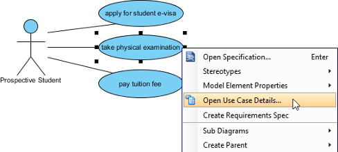
جریان رویدادها و گسترش
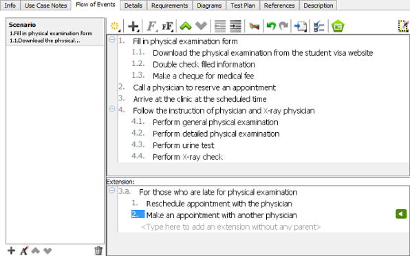
- مسیرهای ثبت شده (به نامسناریوها) از رویدادهای محرک به اهداف
مدلسازی مورد استفاده و UML
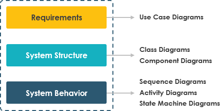
موارد استفاده میتوانند در چندین مرحله از توسعه نرمافزار، مانند برنامهریزی الزامات سیستم، اعتبارسنجی طراحی، آزمایش نرمافزار و ایجاد یک طرح برای کمک آنلاین و راهنماهای کاربری استفاده شوند. بنابراین رابطه نمودار مورد استفاده با سایر نمودارهای UML در SDLC چیست؟
انتخاب مدل مهم است
انتخاب مدلهایی که باید ایجاد شوند تأثیر عمیقی بر نحوه برخورد با یک مشکل و شکلگیری یک راهحل دارد. ما باید مدلهای خود را به خوبی انتخاب کنیم.
- مدلهای صحیح مشکلات توسعهای حیاتی را برجسته خواهند کرد.
- مدلهای نادرست شما را گمراه خواهند کرد و باعث میشوند بر مسائل نامربوط تمرکز کنید.
به عنوان مثال: ما میتوانیم از انواع مختلف نمودارها برای مراحل مختلف در توسعه نرمافزار استفاده کنیم.
منابع
- مروری بر ۱۴ نوع نمودار UML
- نمودار کلاس چیست؟
- نمودار مؤلفه چیست؟
- نمودار استقرار چیست؟
- نمودار شیء چیست؟
- نمودار بسته چیست؟
- نمودار ساختار ترکیبی چیست؟
- نمودار پروفایل چیست؟
- نمودار مورد استفاده چیست؟
- نمودار فعالیت چیست؟
- نمودار ماشین حالت چیست؟
- نمودار توالی چیست؟
- نمودار ارتباط چیست؟
- نمودار مرور تعامل چیست؟
- نمودار زمانبندی چیست؟
- یک جریان اصلی از رویدادها را توصیف میکند (که به آن یک دوره عمل پایه نیز گفته میشود) و ممکن است دیگران را نیز شامل شود، که به آنها گفته میشوداستثناییجریانهای رویداد (که به آنها دورههای عمل جایگزین نیز گفته میشود)
- چند سطحی است، به طوری که یک مورد استفاده میتواند از قابلیتهای مورد استفاده دیگری بهرهبرداری کند.
This post is also available in Deutsch, English, Español, Français, Bahasa Indonesia, 日本語, Polski, Portuguese, Ру́сский, Việt Nam, 简体中文 and 繁體中文.


