این مقاله بر روی مفهوم نمودار فعالیت UML تمرکز دارد. نمودار فعالیت UML یکی دیگر از ابزارهای رایج است که توسط UML برای مدلسازی رفتار دینامیک سیستم استفاده میشود. این نمودار توالی فعالیتها را توصیف میکند و جریان کنترل را از یک فعالیت به فعالیت دیگر نشان میدهد. نمودار فعالیت UML در واقع یک نمودار جریان است.
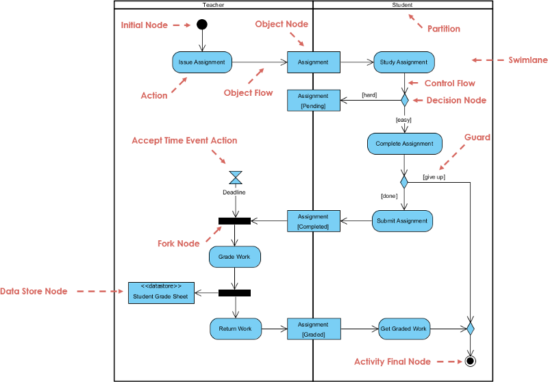
مروری بر نمودار فعالیت UML
اگرچه هر دو نمودار فعالیت UML و نمودارهای حالت نمایانگر ماشینهای حالت هستند، اما تفاوتهای اساسی بین این دو وجود دارد:
- نمودارهای فعالیت UML بر روی جریان کنترل از یک فعالیت به فعالیت دیگر تمرکز دارند که یک جریان پردازش داخلی است؛
- در حالی که نمودارهای حالت بر روی جریان کنترل از یک فعالیت به فعالیت دیگر تمرکز دارند. جریان را از یک حالت به حالت دیگر توصیف میکنند که عمدتاً شامل مشارکت رویدادهای خارجی است.
تفاوت بین نمودار فعالیت UML و نمودار جریان
- نمودار جریان بر روی توصیف فرآیند پردازش تمرکز دارد. ساختار کنترل اصلی آن توالی، انشعاب و چرخه است. بین هر فرآیند پردازش یک توالی و رابطه زمانی دقیق وجود دارد.
- نمودار فعالیت UML قوانین پیروی شده توسط رابطه توالی فعالیتهای شیء را توصیف میکند. این نمودار بر روی رفتار سیستم تمرکز دارد نه بر روی فرآیند سیستم.
- نمودارهای فعالیت UML میتوانند وضعیت فعالیتهای همزمان را نمایش دهند، اما نمودارهای جریان نمیتوانند.
- نمودارهای فعالیت UML شیءگرا هستند، در حالی که نمودارهای جریان فرآیندگرا هستند.
در واقع، میتوانید از یک نمودار فعالیت پایه برای نمایش یک نمودار جریان استفاده کنید، مشابه نمودار معادل:
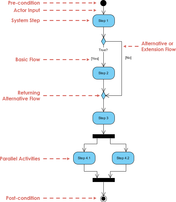
نمایش گرافیکی نمودار فعالیت UML
در UML، نمودارهای فعالیت UML به صورت مستطیلهای گرد نمایش داده میشوند.
خلاصه نشانهگذاری نمودار فعالیت
توضیحات نشانهگذاری نشانهگذاری UML
فعالیت — برای نمایش مجموعهای از اقدامات استفاده میشود

عمل — وظیفهای که باید انجام شود

جریان کنترل — توالی اجرای عملیات را نشان میدهد

جریان شیء — جریان یک شیء را از یک فعالیت (یا عمل) به فعالیت (یا عمل) دیگر نشان میدهد.

گره اولیه — آغاز مجموعهای از اقدامات یا فعالیتها را به تصویر میکشد

گره نهایی فعالیت — تمام جریانهای کنترل و جریانهای شیء را در یک فعالیت (یا عمل) متوقف میکند

گره شیء — نمایانگر شیءای است که به مجموعهای از جریانهای شیء متصل است

گره تصمیم — نمایانگر یک شرط آزمایشی برای اطمینان از این است که جریان کنترل یا جریان شیء فقط به یک مسیر میرود

گره ادغام — مسیرهای تصمیمگیری مختلفی را که با استفاده از یک گره تصمیم ایجاد شدهاند، دوباره به هم میآورد.

گره انشعاب — رفتار را به مجموعهای از جریانهای موازی یا همزمان فعالیتها (یا اعمال) تقسیم میکند

گره پیوستن — مجموعهای از جریانهای موازی یا همزمان فعالیتها (یا اعمال) را دوباره به هم میآورد.

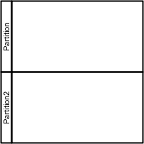
مسیر شناور و تقسیم — روشی برای گروهبندی فعالیتهایی که توسط یک بازیگر در یک نمودار فعالیت انجام میشود یا برای گروهبندی فعالیتها در یک رشته واحد
نمونههای بیشتر از نمودار فعالیت
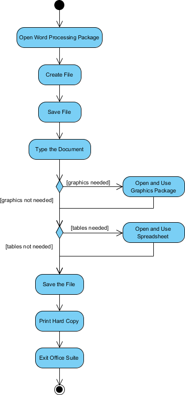
نمودار فعالیت — مدلسازی یک پردازشگر متن
مثال نمودار فعالیت زیر، جریان کار برای یک پردازشگر متن برای ایجاد یک سند را از طریق مراحل زیر توصیف میکند:
- بسته پردازش متن را باز کنید.
- یک فایل ایجاد کنید.
- فایل را با یک نام منحصر به فرد در دایرکتوری خود ذخیره کنید.
- سند را تایپ کنید.
- اگر گرافیک لازم است، بسته گرافیکی را باز کنید، گرافیک را ایجاد کنید و گرافیک را در سند بچسبانید.
- اگر یک صفحه گسترده لازم است، بسته صفحه گسترده را باز کنید، صفحه گسترده را ایجاد کنید و صفحه گسترده را در سند بچسبانید.
- فایل را ذخیره کنید.
- یک نسخه چاپی از سند را چاپ کنید.
- از بسته پردازش کلمات خارج شوید.
مثال نمودار فعالیت — پردازش سفارش
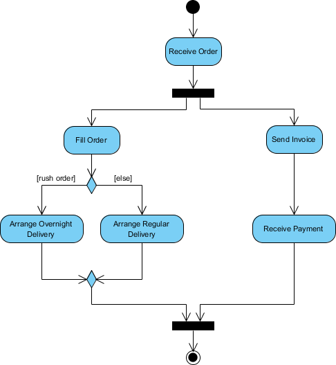
با توجه به توصیف مشکل مربوط به جریان کار برای پردازش یک سفارش، بیایید توصیف را در یک نمایش بصری با استفاده از نمودار فعالیت مدلسازی کنیم:
پردازش سفارش — توصیف مشکل
پس از دریافت سفارش، فعالیتها به دو مجموعه موازی تقسیم میشوند. یک سمت سفارش را پر کرده و ارسال میکند در حالی که سمت دیگر به صدور صورتحساب میپردازد.
در سمت پر کردن سفارش، روش تحویل به صورت شرطی تعیین میشود. بسته به شرایط، یا فعالیت تحویل شبانه یا فعالیت تحویل معمولی انجام میشود.
در نهایت، فعالیتهای موازی برای بستن سفارش ترکیب میشوند.
مثال نمودار فعالیت زیر جریان را به صورت گرافیکی نمایش میدهد.
مثال نمودار فعالیت — ثبتنام دانشجو
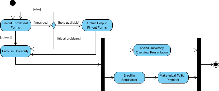
این مثال نمودار فعالیت UML یک فرآیند برای ثبتنام دانشجو در یک دانشگاه را به شرح زیر توصیف میکند:
- یک متقاضی میخواهد در دانشگاه ثبتنام کند.
- متقاضی یک نسخه پر شده از فرم ثبتنام را تحویل میدهد.
- ثبتنامکننده فرمها را بررسی میکند.
- ثبتنامکننده تعیین میکند که فرمها به درستی پر شدهاند.
- ثبتنامکننده به دانشجو اطلاع میدهد که در ارائه کلی دانشگاه شرکت کند.
- ثبتنامکننده به دانشجو کمک میکند تا در سمینارها ثبتنام کند.
- ثبتنامکننده از دانشجو میخواهد که هزینه اولیه تحصیل را پرداخت کند.
نمودار فعالیت — مسیر شناور
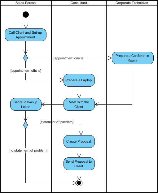
یک مسیر شناور روشی برای گروهبندی فعالیتهای انجام شده توسط یک بازیگر در یک نمودار فعالیت است یا برای گروهبندی فعالیتها در یک رشته واحد. در اینجا یک مثال از نمودار فعالیت مسیر شناور برای مدلسازی ارسال هزینههای کارکنان آورده شده است:
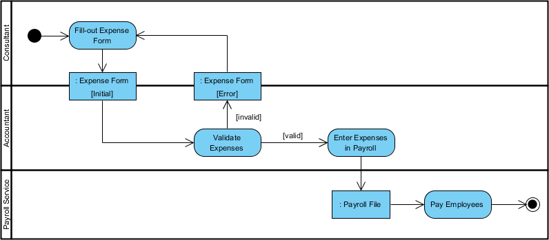
نمودار فعالیت مسیر شناور و غیر مسیر شناور
مثال نمودار فعالیت زیر فرآیند کسبوکار برای ملاقات با یک مشتری جدید را با استفاده از نمودار فعالیت بدون مسیر شناور توصیف میکند.
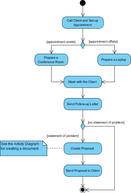
این شکل زیر فرآیند کسبوکار برای ملاقات با یک مشتری جدید را با استفاده از نمودار فعالیت با مسیر شناور توصیف میکند.
آیا میخواهید بیشتر درباره نمودارهای UML به تفصیل بیاموزید؟
- UML چیست؟
- چرا مدلسازی UML؟
- مروری بر ۱۴ نوع نمودار UML
- نمودار کلاس چیست؟
- نمودار مؤلفه چیست؟
- نمودار استقرار چیست؟
- نمودار شیء چیست؟
- نمودار بسته چیست؟
- نمودار ساختار ترکیبی چیست؟
- نمودار پروفایل چیست؟
- نمودار مورد استفاده چیست؟
- نمودار فعالیت چیست؟
- نمودار ماشین حالت چیست؟
- نمودار توالی چیست؟
- نمودار ارتباط چیست؟
- نمودار نمای کلی تعامل چیست؟
- نمودار زمانبندی چیست؟
- نمودار همکاری UML چیست؟
- تفاوت ارتباط UML با تجمیع و ترکیب
- آموزش نمودار کلاس UML
- چگونه محدودیتها را در UML مدلسازی کنیم؟
- نمودار ماشین حالت در مقابل نمودار فعالیت
This post is also available in Deutsch, English, Español, Français, Bahasa Indonesia, 日本語, Polski, Portuguese, Ру́сский, Việt Nam, 简体中文 and 繁體中文.


