زبان مدلسازی یکپارچه یک زبان مدلسازی عمومی استاندارد شده است و امروزه به عنوان یک استاندارد صنعتی de facto مدیریت میشود توسطگروه مدیریت شیء (OMG)UML شامل مجموعهای از تکنیکهای نشانهگذاری گرافیکی برای ایجاد مدلهای بصری برای سیستمهای نرمافزاری است.
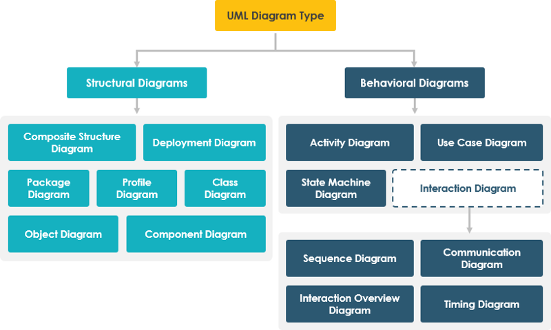
در UML 2.2، ۱۴ نوع نمودار UML وجود دارد که به دو دسته تقسیم میشوند:
- ۷ نوع نمودار اطلاعات ساختاری را نمایندگی میکنند
- ۷ نوع دیگر نمایانگر انواع عمومی نمودار UML برای مدلسازی رفتاری هستند، از جمله چهار نوع که جنبههای مختلف تعاملات را نمایندگی میکنند.
این نمودارها میتوانند به صورت سلسلهمراتبی دستهبندی شوند همانطور که در نقشه نمودار UML زیر نشان داده شده است:
سوال: UML بزرگ و پیچیده است؟
UML واقعاً یک موضوع بزرگ است. UML حجم زیادی از نشانهگذاری نموداری را در ۱۴ نوع مختلف نمودار UML گروهبندی میکند، که هر کدام مدلهای UML متفاوتی دارند و به اهداف مختلف و جنبههای مختلف نیازهای توسعه پاسخ میدهند.
- هر نمودار UML از ۱۴ نوع نمودار UML مجموعه بزرگی از ساختارها و نشانهگذاریها را ارائه میدهد که نیازهای مختلف اکثر پروژههای توسعه نرمافزار را پوشش میدهد.
- مشخصات UML بیش از ۷۰۰ صفحه دارد و به وضوح به عنوان بسیار پیچیده در نظر گرفته میشود و تأثیر منفی بر درک و پذیرش UML دارد.
- به طور معمول، کاربران تمایل دارند تنها بخشی از نمودارها/ساختارهای UML را در نظر بگیرند و استفاده کنند.
پاسخ: یادگیری مهمترین نمودارها و نشانهگذاریهای UML
گریدی بوچ، یکی از مهمترین توسعهدهندگان زبان مدلسازی یکپارچه، بیان کرد که «برای ۸۰٪ از تمام نرمافزارها تنها ۲۰٪ از UML نیاز است».
نظرسنجی UML چه میگوید؟
ما میتوانیم نتایج نظرسنجی UML را با فرض اینکه اگر یک نمودار
- به طور گسترده استفاده میشود، اگر ≥ ۶۰٪ از منابع
- به ندرت استفاده میشود اگر ≤ ۴۰٪ از منابع باشد
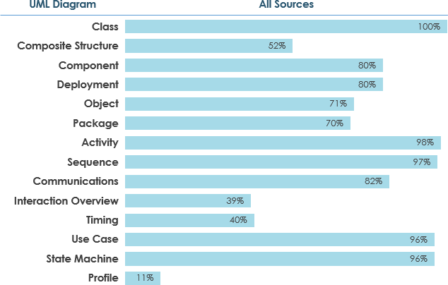
در این مقاله، من تمام ۱۴ نوع نمودار UML را بر اساس ترتیب فراوانی استفاده که در بالا ذکر شد معرفی میکنم:
به عنوان مثال، نمودار کلاس پرکاربردترین نوع است، بنابراین ابتدا در این بخش مورد بحث قرار خواهد گرفت و به همین ترتیب…
نمودار کلاس
در مهندسی نرمافزار، یک نمودار کلاس درزبان مدلسازی یکپارچه (UML)یکنوعی از نمودار ساختار ایستا استکه ساختار یک سیستم را با نشان دادن کلاسهای سیستم، ویژگیهای آنها، عملیات (یا متدها) و روابط بین اشیاء توصیف میکند.
هدف از نمودارهای کلاس
- ساختار ایستای طبقهبندیکنندهها در یک سیستم را نشان میدهد
- نمودار نشانهگذاری پایهای برای سایر نمودارهای ساختاری که توسط UML تجویز شده است ارائه میدهد
- برای توسعهدهندگان و سایر اعضای تیم نیز مفید است
- تحلیلگران کسبوکار میتوانند از نمودارهای کلاس برای مدلسازی سیستمها از منظر کسبوکار استفاده کنند
یک نمودار کلاس UML از موارد زیر تشکیل شده است:
- مجموعهای از کلاسها و
- مجموعهای از روابط بین کلاسها
نمودار کلاس — مثال ابزار نمودار
یک نمودار کلاس ممکن است یادداشتهایی به کلاسها یا روابط متصل داشته باشد. یادداشتها به رنگ خاکستری نشان داده میشوند.
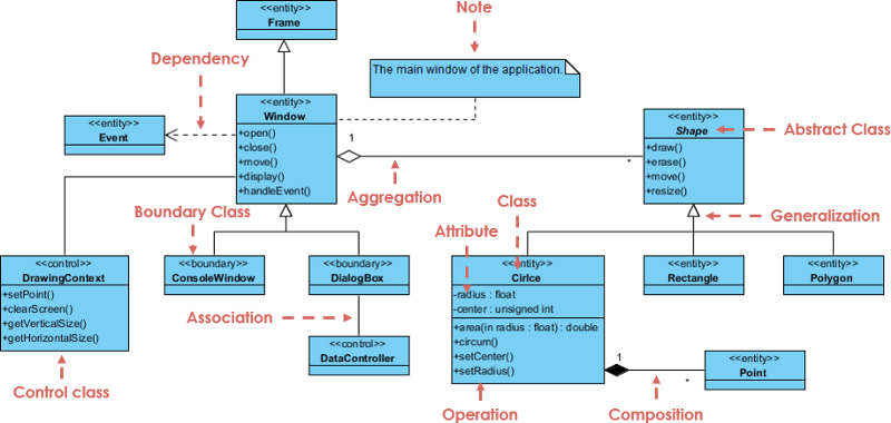
در مثال بالا:
ما میتوانیم معنی نمودار کلاس بالا را با خواندن نکات به شرح زیر تفسیر کنیم.
- شکل یک کلاس انتزاعی است. به صورت ایتالیک نشان داده شده است.
- شکل یک سوپرکلاس است. دایره، مستطیل و چندضلعی از شکل مشتق شدهاند. به عبارت دیگر، یک دایره یک شکل است. این یک رابطه تعمیم / وراثت است.
- بین DialogBox و DataController یک ارتباط وجود دارد.
- شکل بخشی از پنجره است. این یک رابطه تجمیع است. شکل میتواند بدون پنجره وجود داشته باشد.
- نقطه بخشی از دایره است. این یک رابطه ترکیبی است. نقطه نمیتواند بدون دایره وجود داشته باشد.
- پنجره به رویداد وابسته است. با این حال، رویداد به پنجره وابسته نیست.
- ویژگیهای دایره شامل شعاع و مرکز است. این یک کلاس موجودیتی است.
- نام متدهای دایره شامل area()، circum()، setCenter() و setRadius() است.
- پارامتر شعاع در دایره یک پارامتر ورودی از نوع float است.
- متد area() از کلاس دایره یک مقدار از نوع double را بازمیگرداند.
- ویژگیها و نامهای متدهای مستطیل پنهان هستند. برخی دیگر از کلاسها در نمودار نیز ویژگیها و نامهای متدهایشان پنهان هستند.
دومین نوع محبوب نمودار در UML نمودار فعالیت است:
نمودار فعالیت
نمودار فعالیت یک نمودار رفتاری مهم دیگر در UMLنموداری برای توصیف جنبههای دینامیک سیستم است. نمودار فعالیت در واقع نسخه پیشرفتهای از نمودار جریان است که جریان را از یک فعالیت به فعالیت دیگر مدلسازی میکند.
چه زمانی از نمودار فعالیت استفاده کنیم
نمودارهای فعالیت توصیف میکنند که چگونه فعالیتها هماهنگ میشوند تا خدماتی را ارائه دهند که میتواند در سطوح مختلف انتزاع باشد. به طور معمول، یک رویداد باید توسط برخی عملیات به دست آید، به ویژه زمانی که عملیات به منظور دستیابی به چندین چیز مختلف که نیاز به هماهنگی دارند، انجام میشود، یا اینکه چگونه رویدادها در یک مورد استفاده واحد به یکدیگر مربوط میشوند، به ویژه موارد استفادهای که فعالیتها ممکن است همپوشانی داشته باشند و نیاز به هماهنگی دارند. همچنین برای مدلسازی اینکه چگونه مجموعهای از موارد استفاده هماهنگ میشوند تا جریانهای کاری تجاری را نمایندگی کنند، مناسب است.
- شناسایی موارد استفاده کاندید از طریق بررسی جریانهای کاری تجاری
- شناسایی شرایط پیش و پس (زمینه) برای موارد استفاده
- مدلسازی جریانهای کاری بین/درون موارد استفاده
- مدلسازی جریانهای کاری پیچیده در عملیات بر روی اشیاء
- مدلسازی جزئیات فعالیتهای پیچیده در یک نمودار فعالیت سطح بالا
نمودار فعالیت — یادگیری از طریق مثالها
یک نمودار فعالیت پایه — شبیه به نمودار جریان
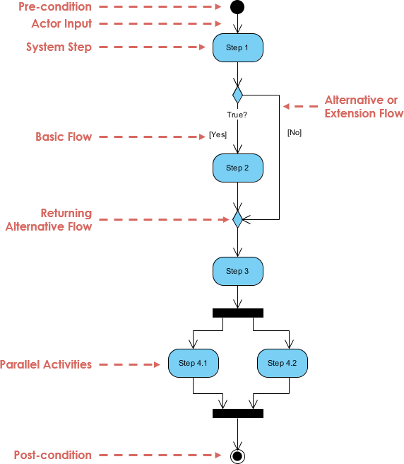
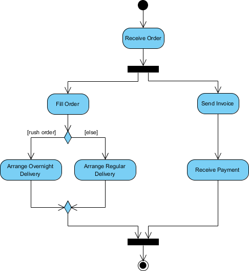
مثال نمودار فعالیت — پردازش سفارش
با توجه به توصیف مشکل مربوط به جریان کاری برای پردازش یک سفارش، بیایید توصیف را در یک نمایش بصری با استفاده از نمودار فعالیت مدلسازی کنیم:
پردازش سفارش — توصیف مشکل
پس از دریافت سفارش، فعالیتها به دو مجموعه موازی تقسیم میشوند. یک طرف سفارش را پر کرده و ارسال میکند در حالی که طرف دیگر به صدور صورتحساب میپردازد.
در سمت پر کردن سفارش، روش تحویل به صورت شرطی تعیین میشود. بسته به شرایط، یا فعالیت تحویل شبانه یا فعالیت تحویل معمولی انجام میشود.
در نهایت، فعالیتهای موازی برای بستن سفارش ترکیب میشوند.
مثال نمودار فعالیت زیر جریان را به صورت گرافیکی تجسم میکند.
سومین نوع نمودار UML که به طور گسترده استفاده میشود، نمودار توالی است:
نمودار توالی
UMLنمودارهای توالی نمودارهای تعامل هستند که جزئیات نحوه انجام عملیات را نشان میدهند. آنها تعامل بین اشیاء را در زمینه یک همکاری ثبت میکنند. نمودارهای توالی بر زمان تمرکز دارند و ترتیب تعامل را به صورت بصری با استفاده از محور عمودی نمودار برای نمایش زمان، اینکه چه پیامهایی ارسال میشود و چه زمانی، نشان میدهند.
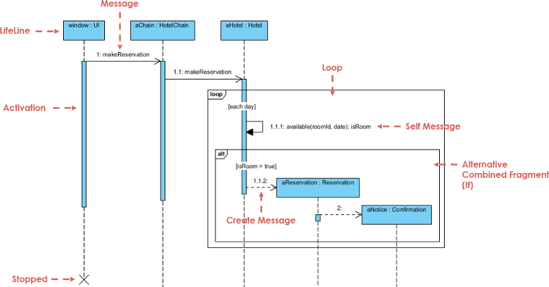
مثال نمودار توالی: سیستم هتل
نمودار توالی یک نمودار تعامل است که جزئیات نحوه انجام عملیات را نشان میدهد — چه پیامهایی ارسال میشود و چه زمانی. نمودارهای توالی بر اساس زمان سازماندهی میشوند. زمان با پایین رفتن از صفحه پیشرفت میکند. اشیاء درگیر در عملیات از چپ به راست بر اساس زمانی که در توالی پیام شرکت میکنند، فهرست میشوند.
در زیر یک نمودار توالی برای ایجاد یک رزرو هتل وجود دارد. شیء آغازگر توالی پیامها یک پنجره رزرو است.
توجه داشته باشید: نمودارهای کلاس و شیء نمای مدل ایستا هستند. نمودارهای تعامل دینامیک هستند. آنها توصیف میکنند که اشیاء چگونه همکاری میکنند.
چهارمین نوع نمودار UML که به طور گسترده استفاده میشود (۹۶٪) عبارتند از:
- نمودار مورد استفاده
- نمودار ماشین حالت
نمودار مورد استفاده
یک UMLنمودار مورد استفاده شکل اصلی نیازمندیهای سیستم/نرمافزار برای یک برنامه نرمافزاری جدید در حال توسعه است. موارد استفاده رفتار مورد انتظار (چه) را مشخص میکنند و نه روش دقیق انجام آن (چگونه).
موارد استفاده پس از مشخص شدن میتوانند به صورت نمایشی متنی و بصری (یعنی نمودار مورد استفاده) نشان داده شوند. یک مفهوم کلیدی در مدلسازی مورد استفاده این است که به ما کمک میکند یک سیستم را از دیدگاه کاربر نهایی طراحی کنیم. این یک تکنیک مؤثر برای ارتباط رفتار سیستم به زبان کاربر با مشخص کردن تمام رفتارهای قابل مشاهده خارجی سیستم است.
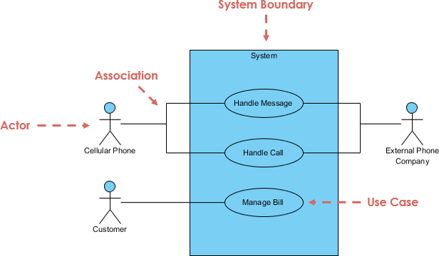
نمودار مورد استفاده در یک نگاه
یک فرم استاندارد از نمودار مورد استفاده در زبان مدلسازی یکپارچه تعریف شده است که در مثال نمودار مورد استفاده زیر نشان داده شده است:
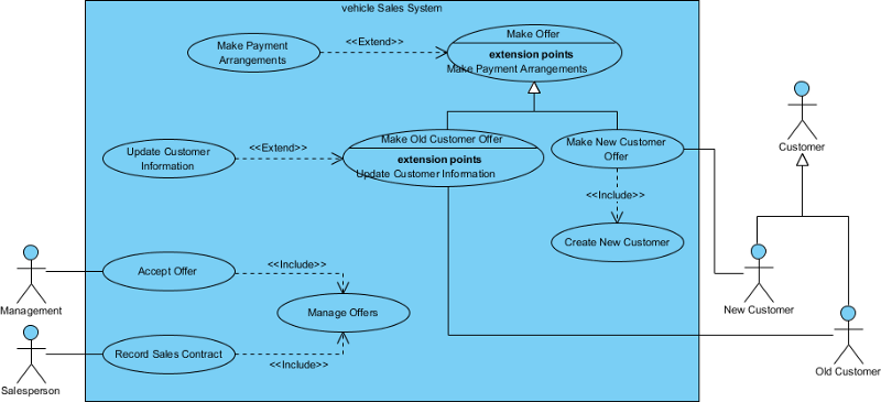
نمودار مورد استفاده — سیستمهای فروش خودرو
شکل زیر یک مثال از نمودار مورد استفاده برای یک سیستم خودرو را نشان میدهد. همانطور که میبینید حتی یک سیستم به بزرگی سیستم فروش خودرو شامل بیش از ۱۰ مورد استفاده نیست! این زیبایی مدلسازی مورد استفاده است.
مدل مورد استفاده همچنین استفاده از گسترش و شامل را نشان میدهد. علاوه بر این، ارتباطاتی وجود دارد که بین بازیگران و موارد استفاده ارتباط برقرار میکند.
نمودار حالت
رفتار یک موجودیت نه تنها نتیجه مستقیم ورودیهای آن است، بلکه به وضعیت قبلی آن نیز بستگی دارد. تاریخچه گذشته یک موجودیت بهترین مدلسازی را میتوان با نمودار ماشین حالت محدود یا به طور سنتی به نام اتوماتا انجام داد.
UMLنمودارهای ماشین حالت (یا گاهی به عنوان نمودار حالت، ماشین حالت یا نمودار حالت نامیده میشوند) وضعیتهای مختلف یک موجودیت را نشان میدهند. نمودارهای ماشین حالت همچنین میتوانند نشان دهند که یک موجودیت چگونه به رویدادهای مختلف با تغییر از یک حالت به حالت دیگر پاسخ میدهد. نمودار ماشین حالت یک نمودار UML است که برای مدلسازی طبیعت دینامیک یک سیستم استفاده میشود.
نوتیشن نمودار ماشین حالت ساده

یک حالت ساده حالتی است که هیچ زیرساختی ندارد. حالتی که زیرحالتها (حالتهای تو در تو) دارد، به آن حالت ترکیبی گفته میشود. زیرحالتها میتوانند به هر سطحی تو در تو باشند. یک ماشین حالت تو در تو ممکن است حداکثر یک حالت اولیه و یک حالت نهایی داشته باشد. زیرحالتها برای سادهسازی ماشینهای حالت پیچیده صاف با نشان دادن اینکه برخی حالات تنها در یک زمینه خاص (حالت محاط) ممکن است، استفاده میشوند.
مثال زیرحالت — هیتر
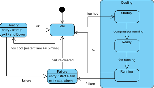
حالتهای تاریخی
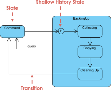
مگر اینکه به طور دیگری مشخص شده باشد، زمانی که یک انتقال وارد یک حالت ترکیبی میشود، عمل ماشین حالت تو در تو دوباره از حالت اولیه شروع میشود (مگر اینکه انتقال به طور مستقیم به یک زیرحالت هدفگذاری شده باشد). حالتهای تاریخی به ماشین حالت اجازه میدهند تا دوباره وارد آخرین زیرحالت فعال قبل از خروج شود حالت ترکیبی. یک مثال از استفاده از حالت تاریخی در شکل زیر ارائه شده است.
استفاده از نمودار ارتباطات طبق نظرسنجی 82% است:
نمودار ارتباطات
UML نمودارهای ارتباطی، مانند نمودارهای توالی — یک نوع نمودار تعامل، نشان میدهد که اشیاء چگونه با یکدیگر تعامل دارند. نمودار ارتباطات یک گسترش از نمودار شیء است که اشیاء را به همراه پیامهایی که از یکدیگر عبور میکنند نشان میدهد. علاوه بر ارتباطات بین اشیاء، نمودار ارتباطات پیامهایی را که اشیاء به یکدیگر ارسال میکنند نشان میدهد.
نمودار ارتباطات در یک نگاه
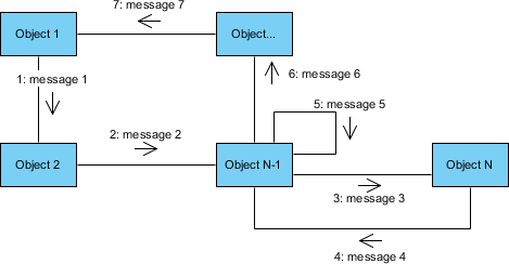
در مثال نشانهگذاری برای یک نمودار ارتباطات، اشیاء (بازیگران در موارد استفاده) با مستطیلها نمایش داده میشوند. در مثال (نمودار ارتباطات عمومی):
- اشیاء عبارتند از Object1، Object2، Object…، ObjectN-1 … و ObjectN.
- پیامهای منتقل شده بین اشیاء با پیکانهای برچسبگذاری شده نمایش داده میشوند که از شیء فرستنده (بازیگر) شروع و به شیء دریافتکننده ختم میشوند.
- پیامهای نمونهای که بین اشیاء منتقل میشوند با برچسب 1: message1، 2: message2، 3: message3 و غیره مشخص شدهاند، که پیشوند عددی به نام پیام نشاندهنده ترتیب آن در توالی است.
- Object1 ابتدا پیام message1 را به Object2 ارسال میکند، سپس Object2 پیام message2 را به ObjectN-1 ارسال میکند و به همین ترتیب.
- پیامهایی که اشیاء به خود ارسال میکنند به عنوان حلقهها نشان داده میشوند (به عنوان مثال، پیام message5).
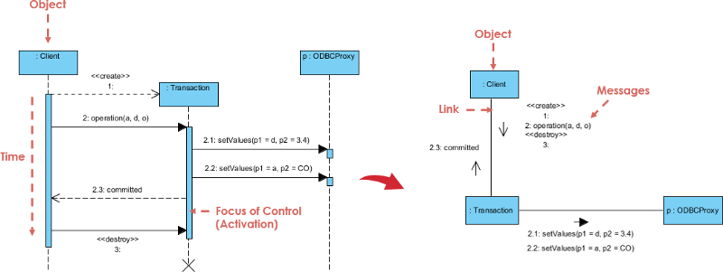
نمودار ارتباطات در مقابل نمودار توالی
نمودار ارتباطات و نمودار توالی مشابه هستند. آنها از نظر معنایی معادل هستند، به این معنی که همان اطلاعات را ارائه میدهند و میتوانید یک نمودار ارتباطات را به نمودار توالی تبدیل کنید و بالعکس. تمایز اصلی بین آنها این است که نمودار ارتباطات عناصر را بر اساس فضا مرتب میکند، در حالی که نمودار توالی بر اساس زمان است.
از دو نوع نمودار تعامل، به نظر میرسد که نمودارهای توالی بسیار بیشتر از نمودارهای ارتباطات استفاده میشوند. پس، چرا باید از نمودارهای ارتباطات استفاده کنید؟ اول از همه، آنها برای تجسم رابطه بین اشیاء که برای انجام یک کار خاص همکاری میکنند بسیار مفید هستند. این موضوع از یک نمودار توالی دشوار است. علاوه بر این، نمودارهای ارتباطات میتوانند به شما در تعیین دقت مدل استاتیک شما (یعنی نمودارهای کلاس) کمک کنند.
استفاده از نمودار مؤلفه و نمودار استقرار هر دو 80% است:
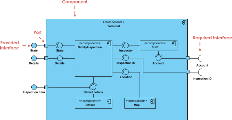
نمودار مؤلفه
UMLنمودارهای مؤلفه در مدلسازی جنبههای فیزیکی سیستمهای شیءگرا که برای تجسم، مشخصسازی و مستندسازی سیستمهای مبتنی بر مؤلفه و همچنین برای ساخت سیستمهای قابل اجرا از طریق مهندسی معکوس و مهندسی رو به جلو استفاده میشوند.
نمودارهای مؤلفه اساساً نمودارهای کلاسی هستند که بر روی مؤلفههای یک سیستم تمرکز دارند و معمولاً برای مدلسازی نمای پیادهسازی استاتیک یک سیستم استفاده میشوند.
نمودار مؤلفه در یک نگاه
یک نمودار مؤلفه سیستم واقعی در حال توسعه را به سطوح مختلف عملکردی تقسیم میکند. هر مؤلفه مسئول یک هدف واضح در کل سیستم است و تنها با سایر عناصر ضروری بر اساس نیاز به دانستن تعامل میکند.
نمودار استقرار
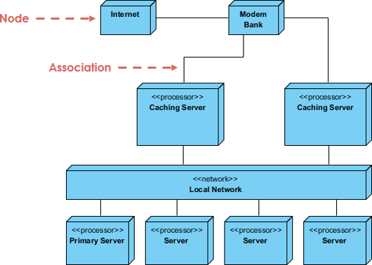
یک UMLنمودار استقرار یک نمودار است که پیکربندی گرههای پردازش زمان اجرا و مؤلفههایی که بر روی آنها وجود دارند را نشان میدهد. نمودارهای استقرار نوعی نمودار ساختاری هستند که در مدلسازی جنبههای فیزیکی یک سیستم شیءگرا استفاده میشوند. آنها معمولاً برای مدلسازی نمای استاتیک استقرار یک سیستم (توپولوژی سختافزار) استفاده میشوند.
نمودار استقرار در یک نگاه
نمودارهای استقرار برای تجسم، مشخصسازی و مستندسازی سیستمهای توکار، کلاینت/سرور و توزیع شده و همچنین برای مدیریت سیستمهای قابل اجرا از طریق مهندسی معکوس و مهندسی رو به جلو مهم هستند.
نمودار استقرار فقط نوع خاصی از نمودار کلاس است که بر روی گرههای یک سیستم تمرکز دارد. به صورت گرافیکی، یک نمودار استقرار مجموعهای از رئوس و قوسها است. نمودارهای استقرار معمولاً شامل موارد زیر هستند:
گرهها
- جعبه 3 بعدی نمایانگر یک گره است، چه نرمافزاری و چه سختافزاری
- گره سختافزاری میتواند با <<استریوتیپ>> مشخص شود
- اتصالات بین گرهها با یک خط نمایش داده میشوند، با <<استریوتیپ>> اختیاری
- گرهها میتوانند درون یک گره قرار گیرند
نشانهگذاریهای دیگر
- وابستگی
- روابط انجمنی.
- ممکن است شامل یادداشتها و محدودیتها نیز باشد.
استفاده از نمودار شیء UML طبق نظرسنجی 71% است:
نمودار شیء
شیء یک نمونه از یک لحظه خاص در زمان اجرا است، شامل اشیاء و مقادیر داده. یک UMLنمودار شیء یک نمونه از یک نمودار کلاس; این یک تصویر فوری از وضعیت دقیق یک سیستم در یک نقطه زمانی را نشان میدهد، بنابراین یک نمودار شیء شامل اشیاء و روابط آنها در یک نقطه زمانی است.
نمودار شیء در یک نگاه
نمودار شیء این رابطه را بین کلاسهای نمونهسازی شده و کلاس تعریف شده نشان میدهد و رابطه بین این اشیاء در سیستم را نیز نشان میدهد. آنها میتوانند برای توضیح بخشهای کوچکتر سیستم شما مفید باشند، زمانی که نمودار کلاس سیستم شما بسیار پیچیده است و همچنین گاهی اوقات برای مدلسازی روابط بازگشتی در نمودار.
بهترین راه برای نشان دادن اینکه یک نمودار شیء چگونه به نظر میرسد، نمایش نمودار شیء مشتق شده از نمودار کلاس مربوطه است.
سیستم مدیریت سفارش زیر روابط آنها را نشان میدهد. این نمودار کلاس کوچک نشان میدهد که یک دپارتمان دانشگاه میتواند شامل دپارتمانهای زیادی باشد و نمودار شیء زیر نمودار کلاس را نمونهسازی میکند و آن را با یک مثال عینی جایگزین میکند.
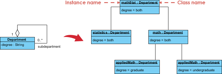
مثال نمودار کلاس به شیء — سیستم سفارش

استفاده از نمودار بسته ۷۰٪ است:
نمودار بسته
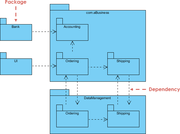
نمودار بسته، نوعی نمودار ساختاری، ترتیب و سازمان عناصر مدل را در پروژههای متوسط تا بزرگ نشان میدهد. نمودار بسته میتواند هم ساختار و هم وابستگیها بین زیرسیستمها یا ماژولها را نشان دهد و دیدگاههای مختلفی از یک سیستم را ارائه دهد، به عنوان مثال، به عنوان یک برنامه چند لایه (که به آن برنامه چند سطحی نیز میگویند) — مدل برنامه چند لایه.
نمودار بسته در یک نگاه
نمودار بسته برای سادهسازی نمودارهای کلاس پیچیده استفاده میشود، شما میتوانید کلاسها را در بستهها گروهبندی کنید. یک بسته مجموعهای از عناصر UML منطقی مرتبط است.
نمودار زیر یک مدل کسب و کار است که در آن کلاسها در بستهها گروهبندی شدهاند:
- بستهها به صورت مستطیلهایی با برچسبهای کوچک در بالا ظاهر میشوند.
- نام بسته بر روی برچسب یا داخل مستطیل است.
- پیکانهای نقطهچین وابستگیها هستند.
- یک بسته به بسته دیگر وابسته است اگر تغییرات در دیگری ممکن است تغییراتی در اولی ایجاد کند.
استفاده از نمودار ساختار ترکیبی ۵۲٪ است:
نمودار ساختار ترکیبی
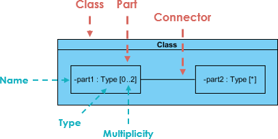
نمودار ساختار ترکیبی یکی از آثار جدید اضافه شده به UML 2.0 است. یک نمودار ساختار ترکیبی یک نمودار ساختاری UML است که شامل کلاسها، رابطها، بستهها و روابط آنها است و نمای منطقی از تمام یا بخشی از یک سیستم نرمافزاری را ارائه میدهد. این نمودار ساختار داخلی (شامل اجزاء و اتصالات) یک طبقهبندیکننده یا همکاری ساختاریافته را نشان میدهد.
یک نمودار ساختار ترکیبی نقش مشابهی با نمودار کلاس دارد، اما به شما اجازه میدهد تا جزئیات بیشتری را در توصیف ساختار داخلی چندین کلاس و نشان دادن تعاملات بین آنها ارائه دهید. شما میتوانید کلاسهای داخلی و اجزاء را به صورت گرافیکی نمایش دهید و ارتباطات را هم بین کلاسها و هم درون کلاسها نشان دهید.
نمودار ساختار ترکیبی در یک نگاه
- نمودارهای ساختار ترکیبی اجزاء داخلی یک کلاس را نشان میدهند.
- اجزاء نامگذاری میشوند: partName:partType[multiplicity]
- کلاسهای تجمیع شده اجزاء یک کلاس هستند اما اجزاء لزوماً کلاسها نیستند، یک جزء هر عنصری است که برای تشکیل کلاس حاوی استفاده میشود.
نمودار زمان تنها ۴۰٪ استفاده دارد و به ندرت توسط کاربران عادی استفاده میشود.
نمودار زمان
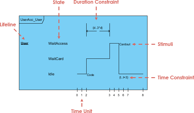
نمودارهای زمان UMLنمودارهای تعامل هستند که برای نشان دادن تعاملات زمانی که هدف اصلی نمودار استدلال درباره زمان است، استفاده میشوند. آنها بر روی تغییر شرایط درون و بین خطهای حیات در امتداد یک محور زمان خطی تمرکز میکنند. نمودارهای زمان رفتار هر دو طبقهبندیکنندههای فردی و تعاملات طبقهبندیکنندهها را توصیف میکنند و توجه را به زمان وقوع رویدادهایی که باعث تغییر در شرایط مدل شده خطهای حیات میشوند، معطوف میکنند.
نمودار زمان در یک نگاه
نمایش زمانبندی وضعیت
تغییرات از یک وضعیتبه دیگری با تغییری در سطح خط حیات. برای مدت زمانی که شیء در یک وضعیت خاص است، زمانبندی موازی با آن وضعیت اجرا میشود. تغییر در وضعیت به صورت یک تغییر عمودی از یک سطح به سطح دیگر ظاهر میشود. علت تغییر، همانطور که در یک نمودار وضعیت یا توالی وجود دارد، دریافت یک پیام، یک رویداد که باعث تغییر میشود، یک شرط درون سیستم، یا حتی فقط گذر زمان است.
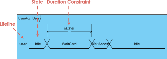
نمایش خط حیات مقدار
شکل زیر یک نوتیشن جایگزین از نمودار زمان UML را نشان میدهد. این نمودار وضعیت شیء را بین دو خط افقی که هر بار وضعیت تغییر میکند، نشان میدهد.
نمودار نمای کلی تعاملی یک نمودار جدید است که در UML 2.0 اضافه شده است:
نمودار نمای کلی تعاملی
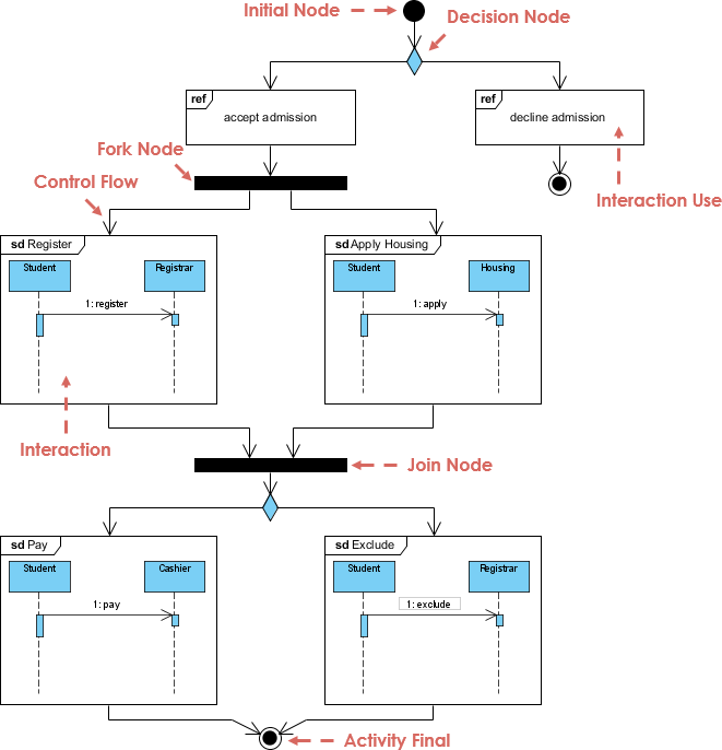
نمودارهای نمای کلی تعامل UML سطح بالایی از انتزاع یک مدل تعامل را فراهم میکنند. این یک نوع از نمودار فعالیت است که در آن گرهها تعاملات یا وقوعهای تعامل هستند.
نمودار نمای کلی تعامل بر روی نمای کلی جریان کنترل تعاملات تمرکز میکند که همچنین میتواند جریان فعالیت بین نمودارها را نشان دهد. به عبارت دیگر، شما میتوانید نمودارهای «واقعی» را به هم متصل کنید و درجه بالایی از قابلیت ناوبری بین نمودارها درون یک نمودار نمای کلی تعامل به دست آورید.
نمودار نمای کلی تعامل در یک نگاه
نمودار نمای کلی تعامل یکی از چهارده نوع نمودار زبان مدلسازی یکپارچه (UML) است که میتواند یک جریان کنترل را با گرههایی که میتوانند نمودارهای تعامل را شامل شوند، به تصویر بکشد و نشان دهد که چگونه یک مجموعه از قطعات ممکن است در سناریوهای مختلف آغاز شود. نمودارهای نمای کلی تعامل بر روی نمای کلی جریان کنترل تمرکز میکنند که در آن گرهها تعاملات (sd) یا استفاده از تعامل (ref).
سایر عناصر نوتیشن برای نمودارهای نمای کلی تعامل همانند نمودارهای فعالیت و توالی هستند. اینها شامل گرههای اولیه، نهایی، تصمیم، ادغام، تقسیم و پیوستن هستند.
کمترین استفاده از نمودار UML، نمودار پروفایل است که تنها ۱۱٪ استفاده دارد:
نمودار پروفایل
به عنوان یک زبان مدلسازی عمومی، UML پایهای پایدار برای انواع مختلف نیازها فراهم میکند. این زبان برای دامنههای خاص کاربرد یا هر فناوری خاصی تعریف نشده است. با این حال، در برخی شرایط، UML بسیار عمومی است و استفاده از آن نیاز به تلاش قابل توجهی دارد. در چنین مواردی، استفاده از زبانی که برای دامنه خاص بهینهسازی شده و بنابراین مفاهیم ویژهای را ارائه میدهد، مزیت دارد.
نمودار پروفایل، نوعی نمودار ساختاری در زبان مدلسازی یکپارچه (UML) است که مکانیزم گسترش عمومی برای سفارشیسازی مدلهای UML برای دامنهها و پلتفرمهای خاص فراهم میکند. مکانیزمهای گسترش اجازه میدهند که معانی استاندارد به صورت کاملاً افزایشی تصحیح شوند و از تناقض آنها با معانی استاندارد جلوگیری کنند. پروفایلها با استفاده از استریوتیپها, تعریف مقادیر برچسبگذاری شده، و محدودیتهاکه به عناصر مدل خاصی مانند کلاسها، ویژگیها، عملیات و فعالیتها اعمال میشوند. یک پروفایل مجموعهای از این گسترشها است که به طور جمعی UML را برای یک دامنه خاص (مانند هوافضا، بهداشت و درمان، مالی) یا پلتفرم (J2EE، .NET) سفارشی میکند.
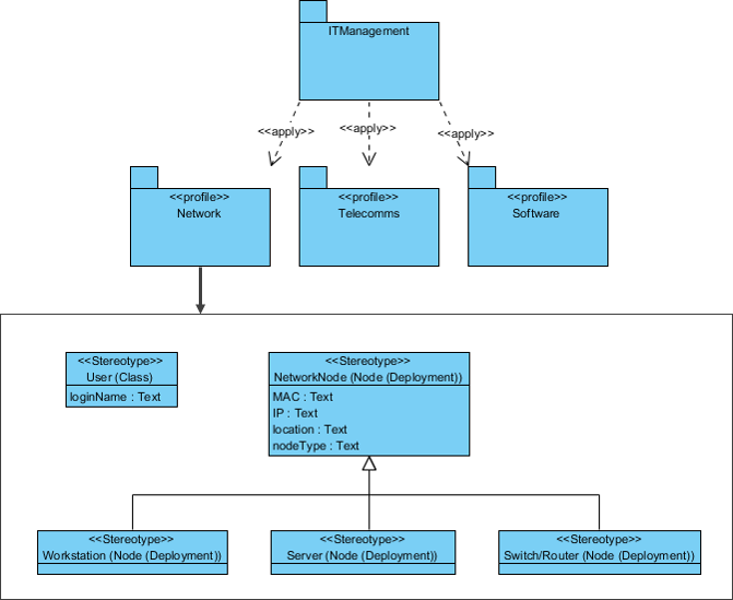
مثال نمودار پروفایل — مدیریت IT
یک پروفایل به یک بسته دیگر اعمال میشود تا استریوتیپهای موجود در پروفایل برای آن بسته در دسترس باشد. تصویر زیر نشان میدهد که پروفایلهای شبکه، مخابرات و نرمافزار به بسته مدیریت IT اعمال میشوند.
به دنبال ابزار طراحی نرمافزار آنلاین رایگان هستید؟
در اینجا مخزن آنلاین Visual Paradigm برای مثالهای طراحی نرمافزار وجود دارد، که عبارت است از:
- رایگان (برای مقاصد شخصی و غیر تجاری)
- آنلاین (بدون نیاز به نصب و پیکربندی)
- پشتیبانی از Google Drive و فضای ذخیرهسازی ابری رایگان
- بسیاری از مثالها
- هر زمان و هر جا از آن استفاده کنید! فقط به یک مرورگر وب نیاز دارید


نمودار جریان داده یوردون دمارکو

This post is also available in Deutsch, English, Español, Français, Bahasa Indonesia, 日本語, Polski, Portuguese, Ру́сский, Việt Nam, 简体中文 and 繁體中文.


