یک نمودار کاربردی UML شکل اصلی نیازمندیهای سیستم/نرمافزار برای یک برنامه نرمافزاری جدید در حال توسعه است. موارد کاربردی رفتار انتظاری (چه) یک سیستم را مشخص میکنند و نه روش دقیق انجام آن (چگونه). یک مجموعه کامل از موارد کاربردی تمام روشهای مختلف استفاده از سیستم را مشخص میکند و بنابراین تمام رفتارهای مورد نیاز سیستم را تعریف میکند و حوزه سیستم را محدود میکند.
یک مفهوم کلیدی در مدلسازی موارد کاربردی این است که به ما کمک میکند یک سیستم را از دیدگاه کاربر نهایی طراحی کنیم. این یک تکنیک مؤثر برای ارتباط رفتار سیستم با اصطلاحات کاربر است و تمام رفتارهای سیستم قابل مشاهده بیرونی را مشخص میکند.
نگاهی به نمودار کاربردی
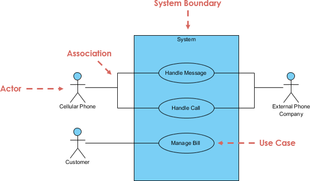
یک شکل استاندارد از نمودار کاربردی در زبان مدلسازی یکپارچه به صورت زیر تعریف شده است:

مورد کاربردی چیست؟
- یک مورد کاربردی مجموعهای از دنبالههای احتمالی از تعاملات بین سیستم در حال بحث و بازیگران خارجی آن است که به یک هدف خاص مرتبط است.
- هر مورد کاربردی یک مسیر کامل از رویدادها در سیستم از دیدگاه کاربر است.
- موارد کاربردی پس از تعریف، میتوانند هم به صورت متنی و هم به صورت تصویری (یعنی نمودار کاربردی) نمایش داده شوند.
- موارد کاربردی روش مورد علاقه جامعه اجزای نرمافزاری و شیگرا برای تعریف نیازمندیها و در واقع راهبری کل فرآیند توسعه نرمافزار است.
- موارد کاربردی معمولاً به وظایف بسیار اصلی میپردازند؛ آنها نیازی نیست که برای هر عملی که کاربر میتواند انجام دهد نوشته شوند.
مزایای رویکرد مورد کاربردی
موارد کاربردی فواید بسیاری فراتر از تعریف نیازمندیهای کاربر ارائه میدهند. موارد کاربردی میتوانند مورد استفاده قرار گیرند:
- موارد کاربردی به شناسایی نیازمندیهای عملکردی یک سیستم کمک میکنند.
- موارد کاربردی قابل ردیابی هستند.
- موارد کاربردی میتوانند به عنوان پایهای برای برآورد، برنامهریزی و اعتبارسنجی تلاش عمل کنند.
- موارد کاربردی میتوانند در هر مرحله از یک روش شناسایی نیازمندیها، به دستورالعملهای توسعه برای برنامهنویسان، به مورد آزمایش و در نهایت به مستندات کاربر تبدیل شوند.
- مسیرهای جایگزین موارد کاربردی رفتارهای اضافی را که میتوانند استحکام سیستم را افزایش دهند، شناسایی میکنند.
- موارد کاربردی به راحتی توسط کاربران تجاری قابل فهم هستند و بنابراین پلی عالی بین توسعهدهندگان نرمافزار و کاربران نهایی بودهاند.
- کلاسهای حوزه کسبوکار و همکاران آنها را شناسایی میکنند.
بازیگر
- فردی که با مورد کاربردی (عملکرد سیستم) تعامل دارد.
- با اسم نامیده میشود.
- بازیگر نقشی در کسبوکار دارد.
- شبیه به مفهوم کاربر، اما یک کاربر میتواند نقشهای مختلفی داشته باشد.
- برای مثال:
- یک استاد میتواند هم مدرس و هم پژوهشگر باشد.
- دو نقش را با دو سیستم ایفا میکند.
- بازیگر موارد کاربردی را راهاندازی میکند.
- بازیگر مسئولیتی نسبت به سیستم دارد (ورودیها) و بازیگر انتظاراتی از سیستم دارد (خروجیها).

مورد کاربردی
- عملکرد سیستم (فرآیند — خودکار یا دستی)
- با فعل + اسم (یا عبارت اسمی) نامیده میشود.
- یعنی انجام کاری
- هر بازیگر باید به یک مورد کاربردی متصل باشد، در حالی که برخی از موارد کاربردی ممکن است به بازیگران متصل نباشند.

پیوند ارتباطی
- مشارکت یک بازیگر در یک مورد کاربردی با اتصال یک بازیگر به یک مورد کاربردی با یک پیوند جامد نشان داده میشود.
- بازیگران ممکن است با ارتباطات به موارد کاربردی متصل شوند، که نشاندهنده این است که بازیگر و مورد کاربردی با استفاده از پیامها با یکدیگر ارتباط برقرار میکنند.

مرز سیستم
- مرز سیستم تمام سیستم احتمالی است که در مستند نیازمندیها تعریف شده است.
- برای سیستمهای بزرگ و پیچیده، هر ماژول ممکن است مرز سیستم باشد.
- برای مثال، برای یک سیستم ERP برای یک سازمان، هر یک از ماژولها مانند پرسنل، حقوق، حسابداری و غیره.
- میتوانند مرز سیستم را برای موارد کاربردی مربوط به هر یک از این عملکردهای کسبوکار تشکیل دهند.
- تمام سیستم میتواند تمام این ماژولها را پوشش دهد و مرز کلی سیستم را نشان دهد.
6 مرحله تحلیل مورد کاربردی
هنگام توسعه موارد کاربردی، باید از یک تقسیمبندی عملکردی شروع کنید — یک فهرست از دستههای عملکردی اصلی سیستم هدف. این کمک میکند تا بفهمیم کدام مناطق نیاز به تمرکز دارند.
مرحله 1 — شناسایی بازیگران: شناسایی کسانی که قرار است به صورت مستقیم از سیستم استفاده کنند. اینها بازیگران هستند.
- یکی از اجزای اصلی توسعه موارد کاربردی، بازیگران هستند.
- یک بازیگر یک نقش خاصی است که توسط یک کاربر سیستم ایفا میشود و یک دسته از کاربران را نشان میدهد که رفتارهای مشابهی در هنگام استفاده از سیستم نشان میدهند.
- بازیگران ممکن است افراد یا سیستمهای رایانهای باشند.
- یک بازیگر اصلی کسی است که هدفی دارد که نیاز به کمک سیستم دارد.
- یک بازیگر فرعی کسی است که سیستم برای رضایت هدف خود نیاز به کمک آن دارد.
- یکی از بازیگران به عنوان سیستم در حال بحث تعیین میشود.
- یک فرد میتواند چندین نقش را ایفا کند و بنابراین چندین بازیگر را نشان دهد، مانند اپراتور سیستم رایانه یا کاربر نهایی.
مرحله 2: انتخاب یکی از آن بازیگران.
- برای شناسایی مورد کاربردی یک سیستم هدف، ما بازیگران سیستم را شناسایی میکنیم.
- یک نقطه شروع خوب این است که طراحی سیستم را بررسی کنیم و بفهمیم که باید به کدام افراد کمک کند.
مرحله 3 — شناسایی موارد کاربردی: تعریف کنید که آن بازیگر چه میخواهد با سیستم انجام دهد. هر یک از این کارهایی که بازیگر میخواهد با سیستم انجام دهد، یک مورد کاربردی میشود.
- آنچه بازیگران میخواهند با سیستم انجام دهند، اهداف میشود.
- هدف نتیجه نهایی اقدامات کاربر است. دو نوع هدف وجود دارد. نوع اول یک هدف سفت و سخت است.
- این هدف باید به طور کامل برآورده شود و نیازمندی حداقل یک سیستم هدف را توصیف میکند.
- برای شناسایی موارد کاربردی، میتوانیم مشخصات نیازمندیها را از دیدگاه یک بازیگر بخوانیم و گفتگوهایی را با کاربرانی که به عنوان بازیگر عمل میکنند، انجام دهیم.
- با تعریف همه چیزی که هر بازیگر میتواند در تعامل با سیستم انجام دهد، عملکرد کامل سیستم تعریف میشود.
مرحله 4 — شناسایی سناریوی معمول مورد کاربردی: برای هر یک از آن موارد کاربردی، مسیر معمول را هنگامی که آن بازیگر از سیستم استفاده میکند، تعیین کنید. آنچه که معمولاً اتفاق میافتد.
- یک مورد کاربردی یک مسیر اصلی و چندین مسیر جایگزین دارد.
- مسیر اصلی سادهترین مسیر است، مسیری که در آن یک درخواست بدون هیچ مشکلی تحویل داده میشود.
- ممکن است مسیرهای جایگزین وجود داشته باشد که تغییرات مسیر اصلی و خطاهایی که ممکن است رخ دهند را توصیف میکنند.
- اینها به عنوان افزونههای مورد کاربردی ثبت میشوند.
مرحله 5 — توسعه توصیف مورد کاربردی: مسیر اصلی را در توصیف مورد کاربردی توصیف کنید.
- سناریوی کاربردی از دیدگاه کاربر با زبانی قابل فهم نوشته میشود.
- مراحل لازم برای دستیابی به هدف شناسایی شده، به عنوان جریان رویدادها نوشته میشود.
مرحله 6 — توسعه مسیرهای جایگزین مورد کاربردی: هنگامی که از مسیر اصلی راضی هستید، حالا جایگزینها را در نظر بگیرید و آنها را به عنوان موارد کاربردی گسترشیافته اضافه کنید.
سناریوهای جایگزین یک مورد کاربردی
یک مورد کاربردی همچنین توصیف میکند که سیستم باید چگونه واکنش نشان دهد وقتی اتفاقات یا درست اتفاق نمیافتند یا درست اتفاق میافتند، اما نه به روشی که در سناریوی اصلی موفقیت توصیف شده است. به این وضعیتها گسترشها میگوییم.
- دو نوع وجود دارد: استثناها و جایگزینها.
- استثناها شرایط خطا هستند (چیزی اشتباه پیش آمده است).
- جایگزینها فقط راه دیگری برای انجام درست کارها هستند.
سطوح جزئیات مورد کاربردی
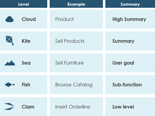
درجه دقت مورد کاربردی به روش سازماندهی اطلاعات در مشخصات موارد کاربردی و در حدودی سطح جزئیات آنها اشاره دارد. رسیدن به سطح مناسب درجه دقت مورد کاربردی ارتباط بین ذینفعان و توسعهدهندگان را آسان میکند و برنامهریزی پروژه را بهبود میبخشد.
آلیستر کاکبرن در نوشتن موارد کاربردی مؤثر به ما راهی آسان برای تصور سطوح مختلف هدف با تصور دریا میدهد:

توجه داشته باشید که:
- در حالی که یک مورد کاربردی ممکن است در مورد تمام جزئیات هر احتمال توضیح دهد، نمودار مورد کاربردی معمولاً برای یک دید سطح بالاتر از سیستم به عنوان نقشههای معماری استفاده میشود.
- نوشتن موارد کاربردی در سطح درشتتر جزئیات با جزئیات کمتر زمانی که لازم نیست، مفید است.
امیدوارم اکنون بتوانید به سؤال “نمودار کاربردی چیست” پاسخ دهید و بتوانید مورد کاربردی را در پروژه خود اعمال کنید. اگر میخواهید در مورد انواع دیگر نمودارهای UML بیشتر بدانید، لطفاً راهنمای UML را مشاهده کنید: بررسی 14 نوع نمودار UML.
منابع
This post is also available in Deutsch, English, Español, Français, Bahasa Indonesia, 日本語, Polski, Portuguese, Ру́сский, Việt Nam, 简体中文 and 繁體中文.


