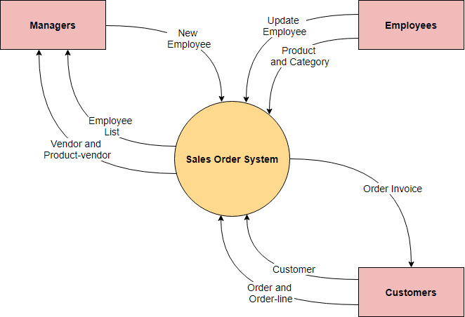
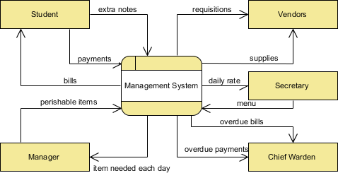
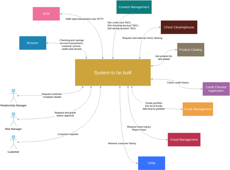
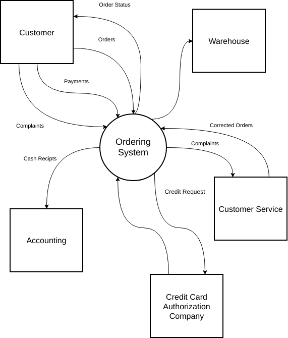
ایننمودار زمینه سیستم (که به عنوان سطح 0 نیز شناخته میشود DFD) بالاترین سطح در نمودار جریان داده است و تنها یک فرآیند را شامل میشود که نمایانگر کل سیستم است و زمینه و مرزهای سیستمی که باید مدلسازی شود را تعیین میکند. این نمودار جریان اطلاعات بین سیستم و نهادهای خارجی، یعنی بازیگران را شناسایی میکند.
نمودارهای زمینه معمولاً در اسناد الزامات گنجانده میشوند. این نمودار باید توسط تمام ذینفعان خوانده شود و بنابراین باید به زبان ساده نوشته شود تا ذینفعان بتوانند پروژه را درک کنند.
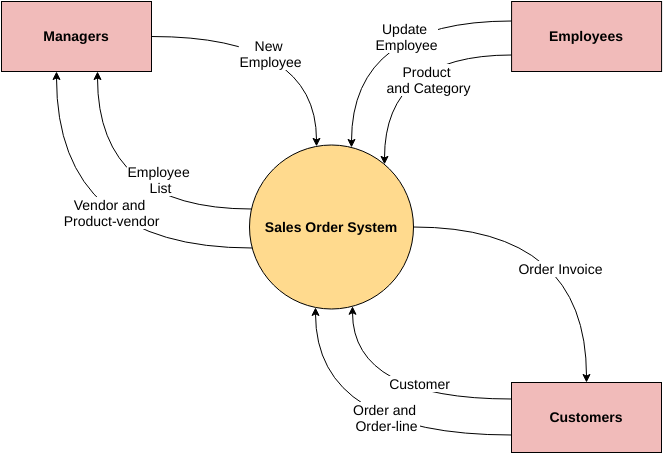
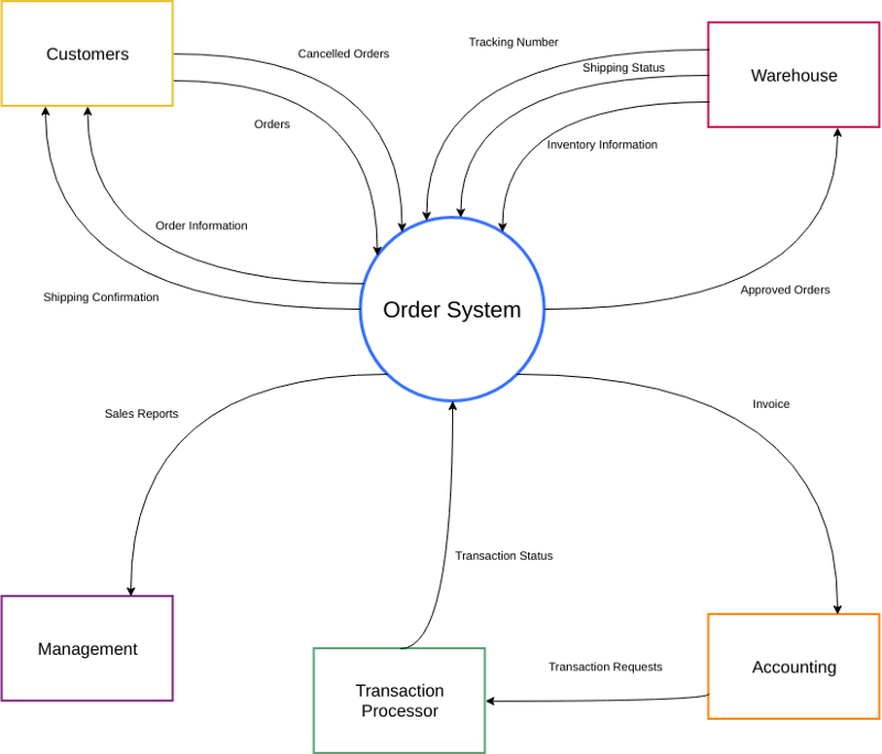
در اینجا یک نمونه نمودار زمینه برای سیستم سفارش فروش آورده شده است:
هدف از نمودار زمینه سیستم
هدف از نمودار زمینه سیستم، تمرکز بر عوامل و رویدادهای خارجی است که باید در هنگام توسعه مجموعهای از الزامات و محدودیتهای سیستم در نظر گرفته شوند. نقشههای زمینه سیستم معمولاً در اوایل یک پروژه برای تعیین دامنه تحقیق استفاده میشوند.
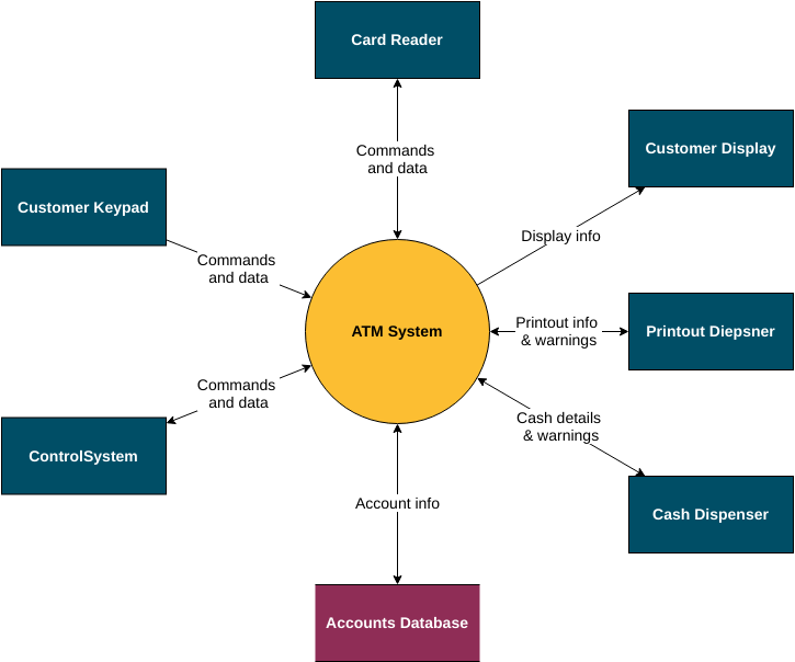
نمودار زمینه سیستم نمایانگر تمام نهادهای خارجی است که ممکن است با سیستم تعامل داشته باشند. کل سیستم نرمافزاری مانند یک فرآیند واحد به نظر میرسد. چنین نموداری سیستمی را در مرکز نشان میدهد، بدون جزئیات ساختار داخلی آن، که توسط تمام نهادهای خارجی و سیستمهای تعاملی در محیط احاطه شده است.
تجزیه از بالا به پایین چیست؟
در طراحی از بالا به پایین، نمای کلی سیستم طراحی میشود، بهطوریکه هر سطح از زیرسیستم مشخص میشود اما جزئیات آن بیان نمیشود. سپس، هر زیرسیستم با جزئیات بیشتری اصلاح میشود، بهعنوان مثال، گاهی به سطوح مختلف زیرسیستم تقسیم میشود تا کل مشخصات به عناصر پایه تجزیه شود.
هدف اصلی طراحی از بالا به پایین، تجزیه یک سیستم به بخشهای کوچکتر به منظور درک زیرسیستمهای آن است. هنگامی که این عناصر پایه شناسایی شدند، میتوان آنها را به راحتی به ماژولهای کامپیوتری تبدیل کرد. هنگامی که ماژولها ساخته شدند، میتوانید به راحتی آنها را کنار هم قرار دهید و کل سیستم را از این عناصر فردی بسازید.
نمودار زمینه سطح بالا
نمودار زمینه نمای کلی میدهد و بالاترین سطح در یک نمودار جریان داده است که تنها یک فرآیند را شامل میشود که نمایانگر کل سیستم است. باید به فرآیندهای اصلی تقسیم شود که جزئیات بیشتری را ارائه میدهند و هر فرآیند اصلی ممکن است بیشتر تقسیم شود تا جزئیات بیشتری ارائه دهد.
- تمام نهادهای خارجی در نمودار زمینه نشان داده میشوند و همچنین جریان دادههای اصلی به و از آنها.
- این نمودار هیچ نوع ذخیرهسازی دادهای ندارد.
- فرآیند واحد در نمودار سطح زمینه، که نمایانگر کل سیستم است، میتواند گسترش یابد تا فرآیندهای اصلی سیستم را در نمودار سطح بعدی، که به آن نمودار 0 گفته میشود، شامل شود.
سطح 1 DFD
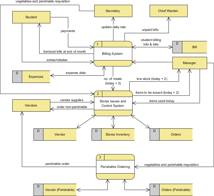
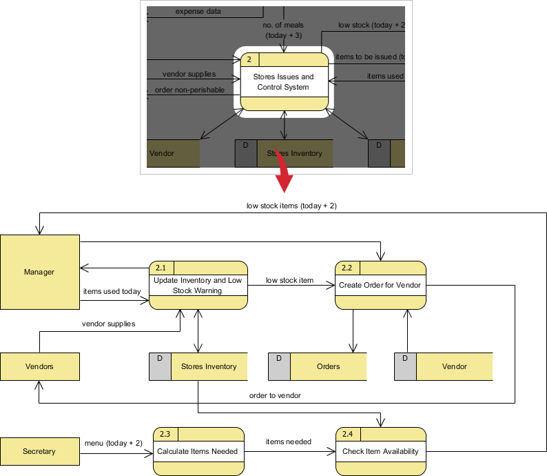
فرآیندها در نمودار 0 (با عدد صحیح) میتوانند بیشتر گسترش یابند تا جزئیات فعالیتهای پردازش را نمایان کنند. مثال زیر سطح بعدی ((نمودار 1) از انفجار فرآیند را نشان میدهد.
توجه داشته باشید که:
اگرچه سطح 1 DFD زیر تنها سه فرآیند دارد، اما ورودیها و خروجیهای زیادی از فرآیندها به نهادهای خارجی وجود دارد و این ممکن است منجر به چند خط متقاطع در بین آنها در نمودار شود؛ برای جلوگیری از این مشکل، میتوانیم از (نمای اصلی و کمکی) چندین نمای از همان نهاد خارجی در DFD استفاده کنیم.
سطح 2 DFD
اگر یک فرآیند با جریان داده زیاد بین چند نهاد خارجی وجود داشته باشد، میتوانیم ابتدا آن فرآیند خاص و نهادهای خارجی مرتبط را به یک نمودار جداگانه مشابه نمودار زمینه استخراج کنیم، قبل از اینکه فرآیند را به یک سطح جداگانه از DFD اصلاح کنیم؛ و به این ترتیب میتوانید اطمینان حاصل کنید که بین آنها سازگاری بیشتری وجود دارد.
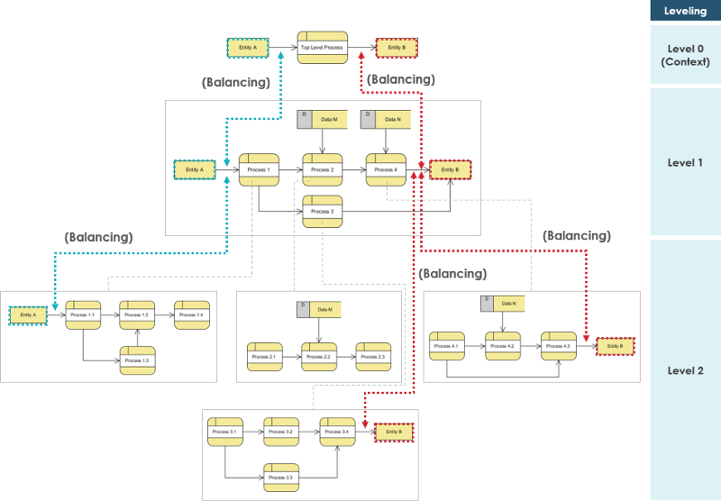
سازگاری مدل DFD بین سطوح
هنگام انجام تجزیه از بالا به پایین به یک DFD به DFDهای سطح پایینتر، ورودیها و خروجیها باید بین سطوح DFDها حفظ شوند. به عنوان مثال، سطح n و n+1 باید ورودیها و خروجیهای یکسانی داشته باشند.
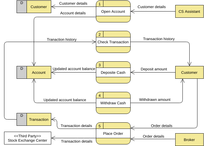
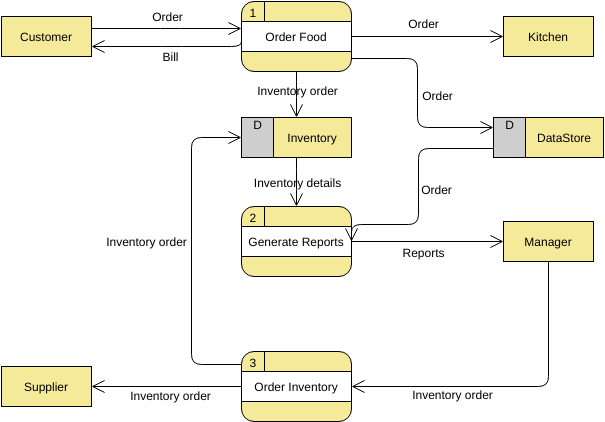
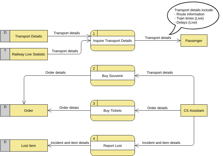
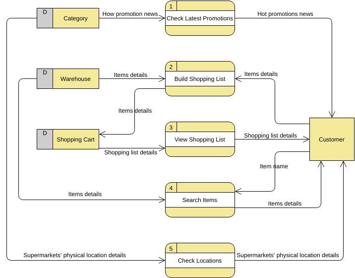
بیشتر بیاموزید با مثالها
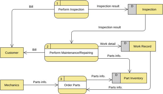
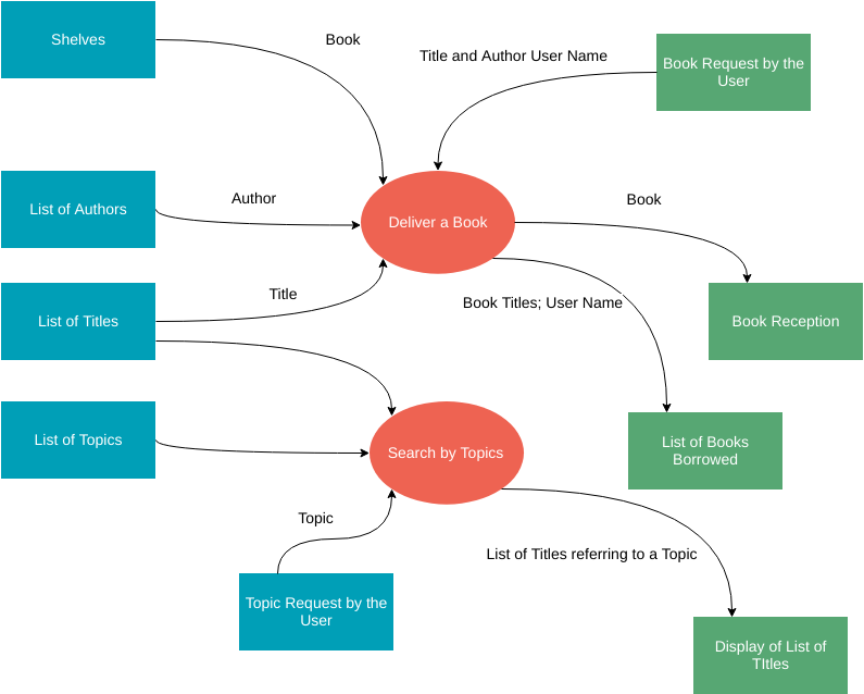
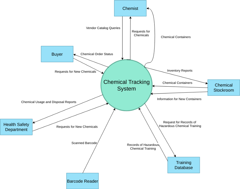
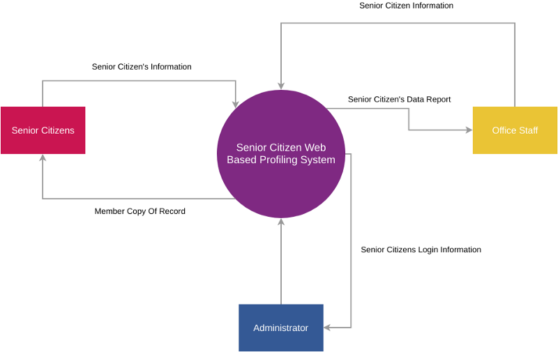
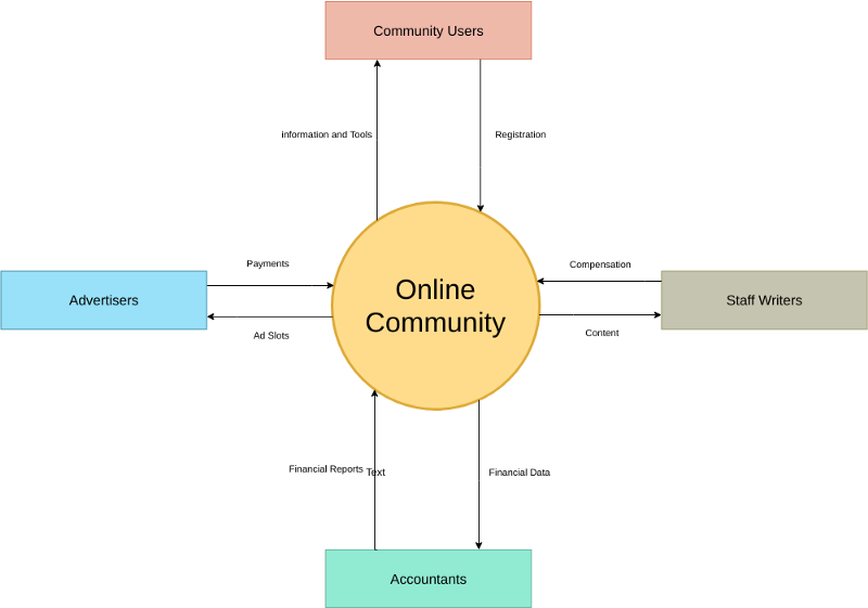
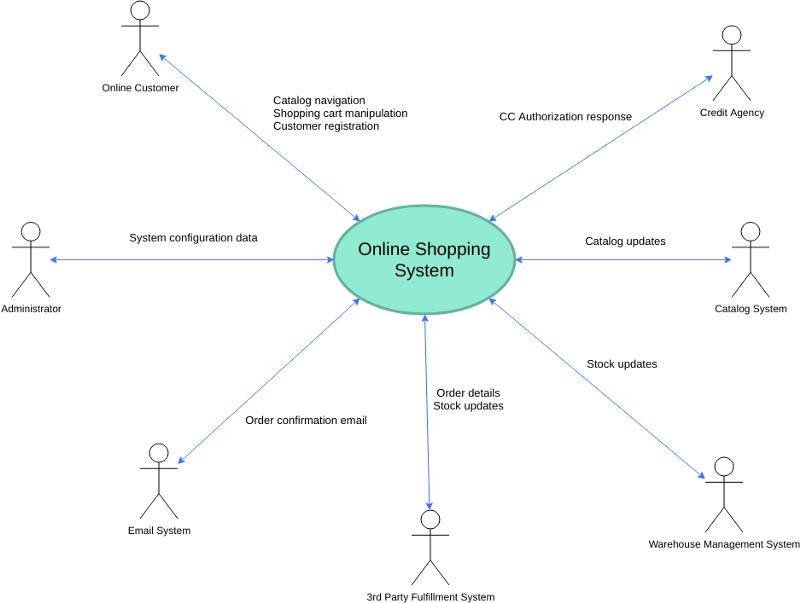
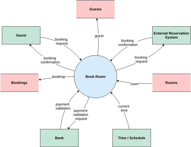
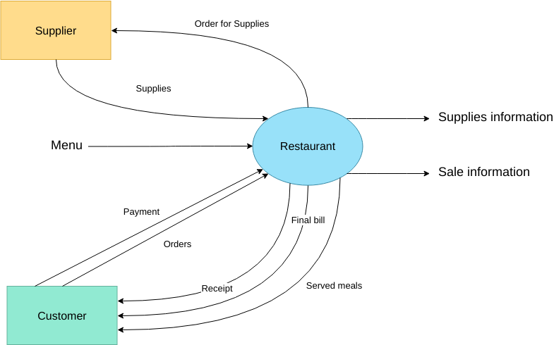
به کمی الهام نیاز دارید؟ در اینجا چند نمونه از نمودارهای جریان داده برای کمک به شما در شروع آورده شده است.
روی یک نمودار کلیک کنید تا آن را مشاهده کنید، یا روی دکمه ویرایش کلیک کنید تا ویرایش را شروع کنید.
(*توسطVisual Paradigm Online)
This post is also available in Deutsch, English, Español, Français, Bahasa Indonesia, 日本語, Polski, Portuguese, Ру́сский, Việt Nam, 简体中文 and 繁體中文.


