Analisis Pohon Kesalahan diperkenalkan pada tahun 1962 oleh Bell Laboratories dan merupakan salah satu yang paling banyak digunakan untuk menyelesaikan berbagai masalah mulai dari keselamatan hingga masalah manajemen.
Analisis pohon kesalahan (FTA) adalah analisis kesalahan deduktif dari atas ke bawah di mana logika Boolean digunakan bersamaan dengan serangkaian peristiwa tingkat rendah untuk menganalisis keadaan tak terduga dari sistem. Metode analisis ini terutama digunakan dalam rekayasa keselamatan dan rekayasa keandalan untuk memahami bagaimana sistem gagal, menentukan cara terbaik untuk mengurangi risiko, dan menentukan (atau merasakan) tingkat kejadian insiden keselamatan atau kegagalan tingkat sistem tertentu (fungsional).
Tujuan dari Analisis Pohon Kesalahan?
Tujuan utama dari analisis pohon kesalahan adalah untuk membantu mengidentifikasi penyebab potensial dari kesalahan sistem sebelum kesalahan terjadi. Anda juga dapat menggunakan metode analitis atau statistik untuk mengevaluasi probabilitas peristiwa puncak. Perhitungan ini mencakup informasi keandalan dan pemeliharaan kuantitatif dari sistem, seperti probabilitas kegagalan, tingkat kegagalan, dan tingkat perbaikan. Setelah menyelesaikan FTA, Anda dapat fokus pada peningkatan keamanan dan keandalan sistem.
Analisis pohon kesalahan yang khas dimulai dengan kesalahan potensial, dan kemudian bekerja mundur melalui representasi visual yang disebut diagram pohon kesalahan untuk menentukan faktor-faktor yang mungkin mempengaruhi. Pohon kesalahan mengadopsi pendekatan dari atas ke bawah, dimulai dengan hasil (kondisi kesalahan potensial), dan kemudian mengevaluasi faktor-faktor yang dapat menyebabkan kesalahan.
Siapa analisis pohon kesalahan
FTA diterapkan pada industri dirgantara, tenaga nuklir, kimia, farmasi, petrokimia, dan industri berisiko tinggi lainnya; Ini juga digunakan untuk tujuan debugging dalam rekayasa perangkat lunak, yang terkait erat dengan teknologi penghapusan penyebab yang digunakan untuk mendeteksi bug.
Notasi FTA
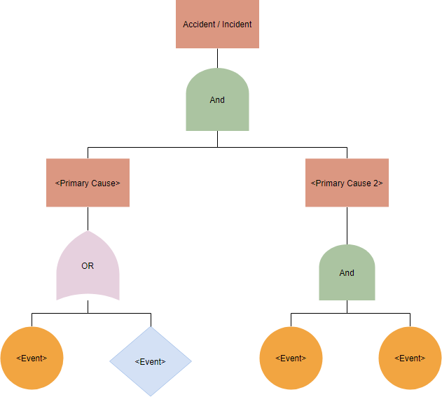
Analisis Pohon Kesalahan menggunakan beberapa simbol dasar untuk menggambarkan berbagai titik, penyebab, dan efek dalam suatu proses. Ada banyak simbol, tetapi berikut adalah beberapa dasar untuk membantu Anda memulai merancang diagram pohon kesalahan.
Simbol digunakan untuk mewakili berbagai peristiwa dan menggambarkan hubungan:
Simbol Gerbang

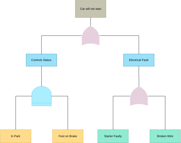
Gerbang Dan — mewakili kondisi di mana semua peristiwa yang ditunjukkan di bawah gerbang (gerbang input) harus ada agar peristiwa yang ditunjukkan di atas gerbang (peristiwa output) dapat terjadi. Ini berarti peristiwa output hanya akan terjadi jika semua peristiwa input ada secara bersamaan.

Gerbang Atau — mewakili situasi di mana salah satu peristiwa yang ditunjukkan di bawah gerbang (gerbang input) akan mengarah pada peristiwa yang ditunjukkan di atas gerbang (peristiwa output). Peristiwa akan terjadi jika hanya satu atau kombinasi dari peristiwa input yang ada.
Simbol Peristiwa
Ada lima jenis simbol peristiwa:

Persegi Panjang — Persegi panjang adalah blok bangunan utama untuk pohon analitis. Ini mewakili peristiwa negatif dan terletak di bagian atas pohon dan dapat terletak di seluruh pohon untuk menunjukkan peristiwa lain yang dapat diuraikan lebih lanjut. Ini adalah satu-satunya simbol yang akan memiliki gerbang logika dan peristiwa input di bawahnya.

Lingkaran — Lingkaran mewakili peristiwa dasar dalam pohon. Ini ditemukan di tingkat bawah pohon dan tidak memerlukan pengembangan atau pemecahan lebih lanjut. Tidak ada gerbang atau peristiwa di bawah peristiwa dasar.

Berlian — Berlian mengidentifikasi peristiwa terminal yang belum berkembang. Peristiwa semacam itu tidak sepenuhnya berkembang karena kurangnya informasi atau signifikansi. Cabang pohon kesalahan dapat berakhir dengan berlian. Misalnya, sebagian besar proyek memerlukan personel, prosedur, dan perangkat keras. Pengembang pohon mungkin memutuskan untuk berkonsentrasi pada aspek personel dari prosedur dan bukan aspek perangkat keras atau prosedural. Dalam hal ini, pengembang akan menggunakan berlian untuk menunjukkan “prosedur” dan “perangkat keras” sebagai peristiwa terminal yang belum berkembang.

Oval — Simbol oval mewakili situasi khusus yang hanya dapat terjadi jika keadaan tertentu terjadi. Ini dijelaskan dalam simbol oval. Contoh dari ini mungkin jika saklar harus dipindahkan dalam urutan tertentu sebelum suatu tindakan dilakukan.

Segitiga — Segitiga menandakan transfer cabang pohon kesalahan ke lokasi lain dalam pohon. Di mana segitiga terhubung ke pohon dengan panah, semua yang ditunjukkan di bawah titik koneksi dipindahkan ke area lain dari pohon. Area ini diidentifikasi oleh segitiga yang sesuai yang terhubung ke pohon dengan garis vertikal. Huruf, angka, atau gambar mengidentifikasi satu set simbol transfer dari yang lain. Untuk menjaga kesederhanaan pohon analitis, simbol transfer harus digunakan dengan hemat.
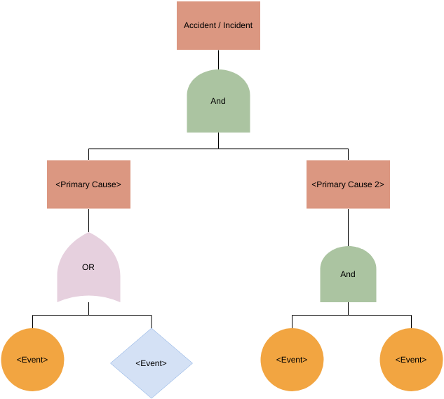
Ilustrasi Diagram Pohon Kesalahan Umum
Langkah-langkah pengembangan pohon kesalahan
Untuk melakukan FTA yang komprehensif, ikuti langkah-langkah ini:
- Tentukan sistem. Ini mencakup ruang lingkup analisis termasuk mendefinisikan apa yang dianggap sebagai kegagalan. Ini menjadi penting ketika suatu sistem mungkin memiliki elemen yang gagal atau satu fungsi gagal dan sisa sistem masih beroperasi.
- Tentukan kesalahan tingkat atas. Tentukan kondisi kesalahan, dan catat kegagalan tingkat atas.
- Identifikasi penyebab kesalahan tingkat atas. Menggunakan informasi teknis dan penilaian profesional, tentukan kemungkinan alasan terjadinya kegagalan. Ingat, ini adalah elemen tingkat dua karena mereka berada tepat di bawah kegagalan tingkat atas dalam pohon.
- Identifikasi tingkat peristiwa berikutnya. Terus uraikan setiap elemen dengan gerbang tambahan ke tingkat yang lebih rendah. Pertimbangkan hubungan antara elemen untuk membantu Anda memutuskan apakah akan menggunakan gerbang logika “dan” atau “atau.”
- Tambahkan probabilitas ke peristiwa. Jika memungkinkan, evaluasi probabilitas terjadinya untuk masing-masing elemen tingkat terendah dan hitung probabilitas statistik dari bawah ke atas.
- Selesaikan dan tinjau diagram lengkap. Rantai hanya dapat diakhiri dalam kesalahan dasar: manusia, perangkat keras, atau perangkat lunak.
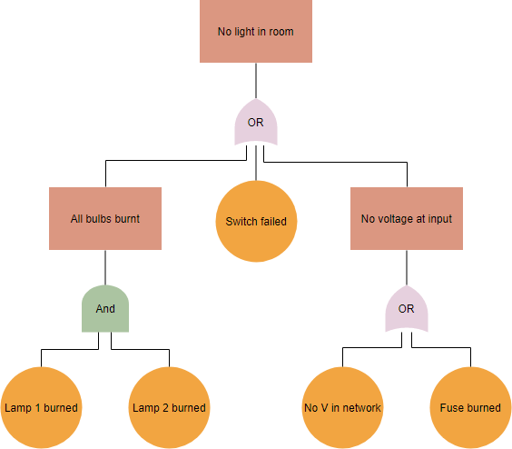
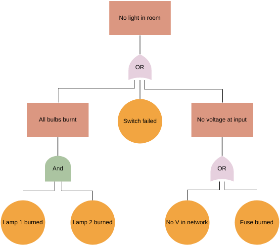
Contoh Diagram Pohon Kesalahan — Lampu tidak dapat menyala
Mari kita lihat contoh analisis pohon kesalahan dasar: Anda membalik saklar untuk menyalakan lampu, tetapi lampu tidak menyala. Kondisi kesalahannya adalah “Tidak ada cahaya di ruangan,” jadi itu adalah awal dari diagram.
Selanjutnya, apa saja alasan potensial lampu tidak menyala?
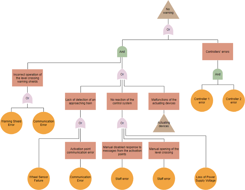
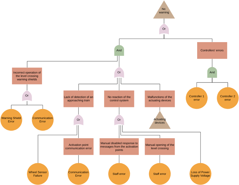
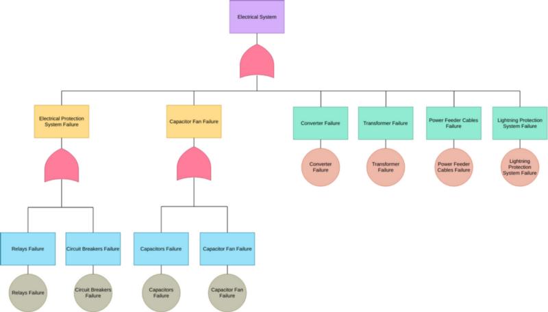
Contoh Pohon Kesalahan — Template Sistem tanpa Peringatan
Pembuat Pohon Kesalahan Daring
Visual Paradigm Online adalah salah satu dari sedikit perangkat lunak di pasar saat ini yang mendukung perangkat lunak analisis pohon kesalahan. Apakah Anda seorang pemula atau profesional, menggambar analisis pohon kesalahan sangat sederhana dan intuitif menggunakan kumpulan simbol dan template analisis pohon kesalahan yang kaya dari VP Online. VP Online adalah perangkat lunak pemetaan daring yang berjalan di perangkat apa pun, di browser mana pun.
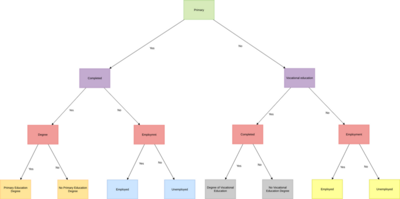
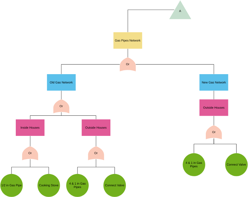
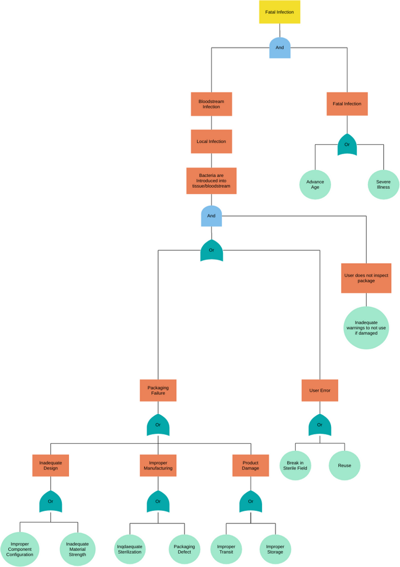
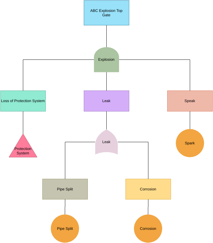
Belajar dengan Contoh: Template Pohon Kesalahan
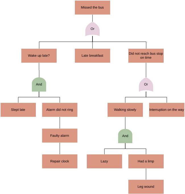
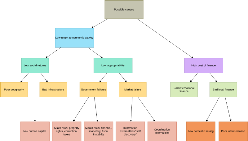
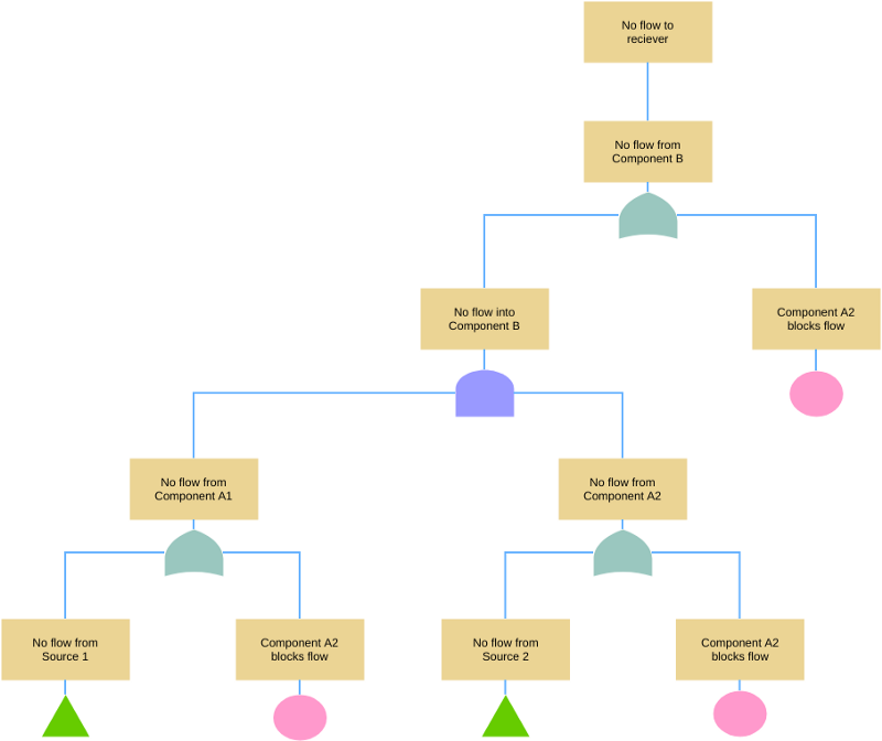
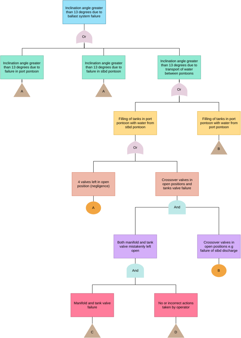
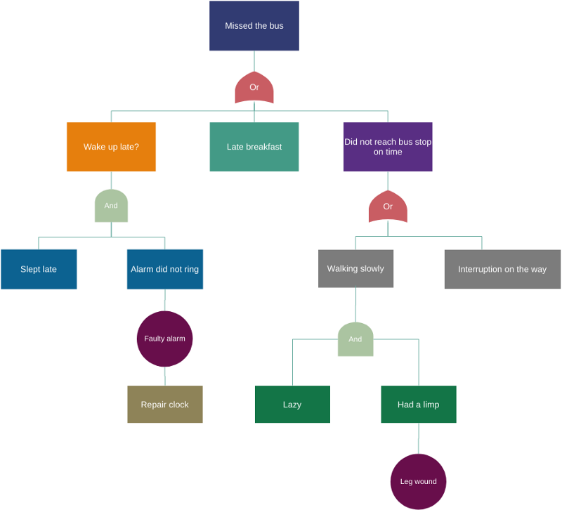
Sekumpulan template analisis pohon kesalahan tersedia. Apakah Anda perlu mengembangkan analisis pohon kesalahan, atau hanya untuk mendapatkan beberapa ide dan memodifikasi template agar sesuai dengan kebutuhan Anda.
This post is also available in Deutsch, English, Español, فارسی, Français, 日本語, Polski, Portuguese, Ру́сский, Việt Nam, 简体中文 and 繁體中文.


