Apa itu UML?
UML adalah singkatan dari Unified Model Language, yang merupakan bahasa pemodelan standar yang terdiri dari 14 jenis diagram UML yang berbeda.
Mengapa menggunakan UML?
Dengan menggunakan UML, seluruh desain perangkat lunak lebih mudah dibaca dan dipahami sebelum pengembangan perangkat lunak, sehingga mengurangi risiko pengembangan. Selain itu, ini memfasilitasi komunikasi antara berbagai pengembang.
UML menyediakan bahasa pemodelan yang sangat ekspresif yang memungkinkan orang-orang yang berbeda dalam proses pengembangan perangkat lunak untuk mendapatkan informasi yang mereka minati.
Tujuan utama UML dapat dirangkum sebagai berikut:
- Memberikan pengguna bahasa pemodelan visual yang ekspresif dan siap pakai sehingga mereka dapat mengembangkan dan mengkomunikasikan model yang bermakna dalam upaya tim kolaboratif.
- Menyediakan mekanisme ekstensi dan spesialisasi untuk konsep inti.
- Independen dari bahasa pemrograman dan proses pengembangan tertentu.
- Menyediakan dasar formal untuk memahami bahasa pemodelan.
- Mendorong pengembangan pasar untuk alat berorientasi objek.
- Dukungan untuk konsep pengembangan tingkat tinggi seperti kolaborasi, kerangka kerja, pola, dan komponen.
- Mengintegrasikan Praktik Terbaik.
Apa itu diagram UML?
- Diagram UML dibagi menjadi diagram struktural dan diagram perilaku.
- Diagram struktur dibagi menjadi diagram kelas, diagram profil, diagram komponen, diagram struktur komposit, diagram objek, diagram penyebaran, dan diagram paket.
- Diagram perilaku dibagi menjadi diagram aktivitas, diagram kasus penggunaan, diagram mesin keadaan, dan diagram interaksi.
- Diagram interaksi dibagi lebih lanjut menjadi diagram urutan, diagram urutan, diagram komunikasi, dan diagram gambaran interaksi.
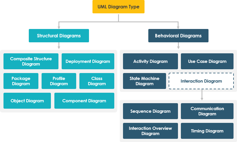
14 Jenis Diagram UML
- Diagram kelas – Sebuah diagram kelas adalah diagram statis yang menggambarkan struktur sistem dengan menunjukkan kelas-kelasnya dan properti serta operasinya, serta hubungan antara objek.
- Diagram Kasus Penggunaan – Sebuah diagram kasus penggunaan terdiri dari kasus penggunaan, peran, dan hubungan di antara mereka. Ini menunjukkan bagaimana pengguna berinteraksi dengan sistem dan mendefinisikan spesifikasi dari kasus penggunaan.
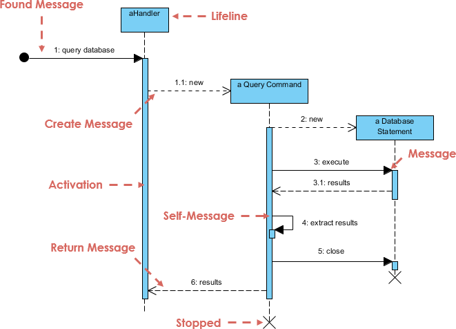
- Diagram urutan – Sebuah diagram urutan adalah model untuk komunikasi antara objek secara berurutan. Ini menunjukkan urutan tepat objek, kelas, dan peran serta informasi yang terlibat dalam sebuah skenario. Ini terdiri dari garis vertikal yang merupakan garis hidup dan garis horizontal pesan.
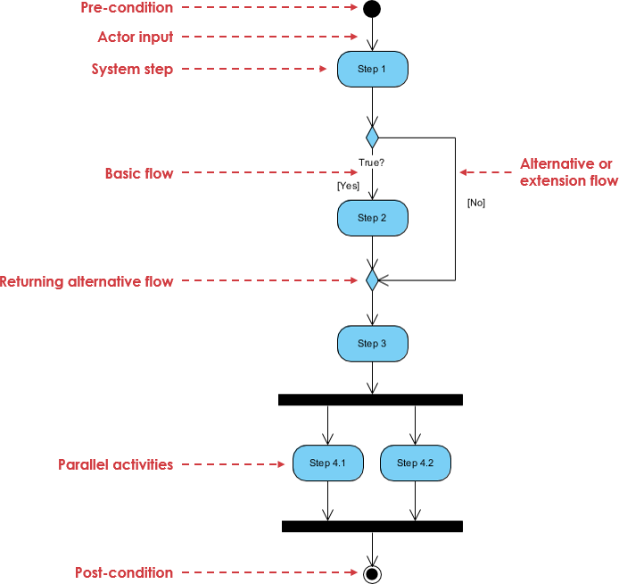
- Diagram aktivitas – Sebuah diagram aktivitas adalah diagram perilaku yang menunjukkan skenario dalam hal aliran tindakan. Ini memodelkan urutan tindakan, keputusan berbasis kondisi, cabang bersamaan, dan berbagai loop.
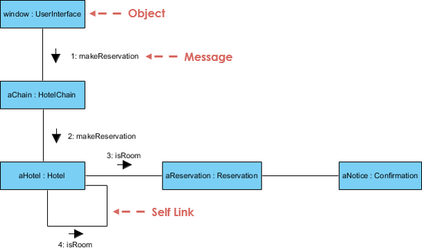
- Diagram komunikasi – Sebuah diagram komunikasi menunjukkan interaksi antara objek dan bagian dalam bentuk pesan, yang diwakili oleh garis hidup. Diagram komunikasi adalah bentuk modifikasi dari diagram urutan UML, tetapi berbeda dari itu karena elemen-elemennya tidak perlu diurutkan secara horizontal dan dapat memiliki posisi apa pun dalam diagram.
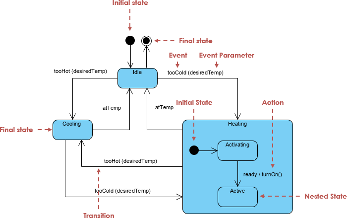
- Diagram Mesin Keadaan – Sebuah diagram mesin keadaan menggambarkan keadaan suatu entitas (perangkat, proses, program, perangkat lunak, modul, dll.) dan transisi antara keadaan. Kondisi-kondisi tersebut menentukan kapan transisi dari satu keadaan ke keadaan lain dapat digunakan.
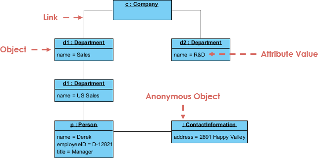
- Diagram objek – Sebuah diagram objek adalah diagram UML terstruktur. Ini menggambarkan sistem atau bagiannya pada waktu tertentu. Ini memodelkan instansi, nilai-nilai mereka, dan hubungan. Ini dapat digunakan untuk menunjukkan contoh struktur data.
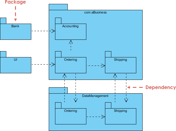
- Diagram paket – Sebuah diagram paket menunjukkan ketergantungan antara paket dalam sebuah model. Ini menggambarkan struktur dan organisasi proyek berskala besar.
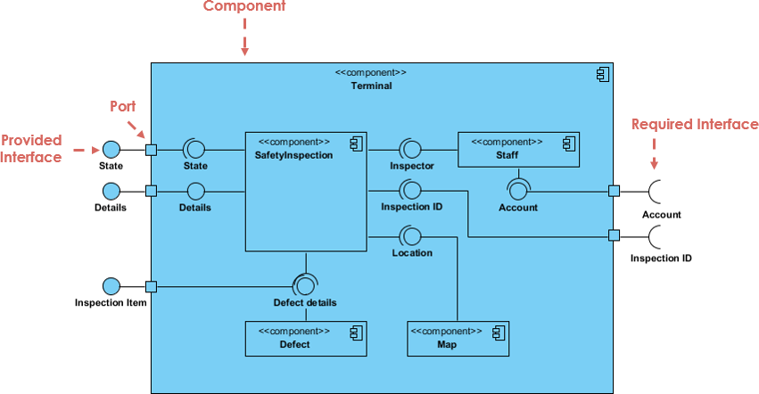
- Diagram komponen – Sebuah diagram komponen memberikan pandangan tentang sistem yang kompleks. Ini menggambarkan antarmuka yang disediakan dan/atau diperlukan oleh berbagai bagian sistem dan hubungan antara bagian-bagian tersebut. Bagian-bagian ini diwakili oleh komponen dan artefak lainnya.
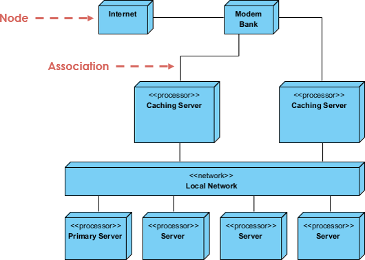
- Diagram Penyebaran – Diagram penyebaran menggambarkan penyebaran artefak pada node jaringan. Ini digunakan untuk menunjukkan lokasi artefak (perangkat lunak, sistem, modul, dll.) pada node fisik (perangkat keras, server, basis data, dll.) dan hubungan antara bagian-bagian tertentu dari solusi.
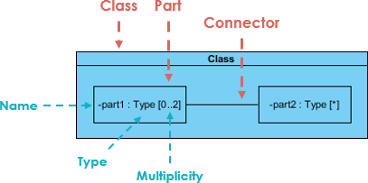
- Diagram Struktur Komposit – Diagram struktur komposit menunjukkan struktur internal dari sebuah pengklasifikasi, bagian-bagiannya dan port, melalui mana ia berkomunikasi dengan lingkungannya. Ini memodelkan kolaborasi, di mana setiap elemen memiliki peran yang ditentukan.
- Gambaran Interaksi – Diagram Gambaran Interaksi memberikan pandangan tingkat tinggi tentang interaksi dalam sebuah sistem atau subsistem. Ini menggambarkan proses dengan cara yang mirip dengan diagram aktivitas, tetapi menggunakan diagram interaksi lain dan referensi interaksi daripada node aksi.
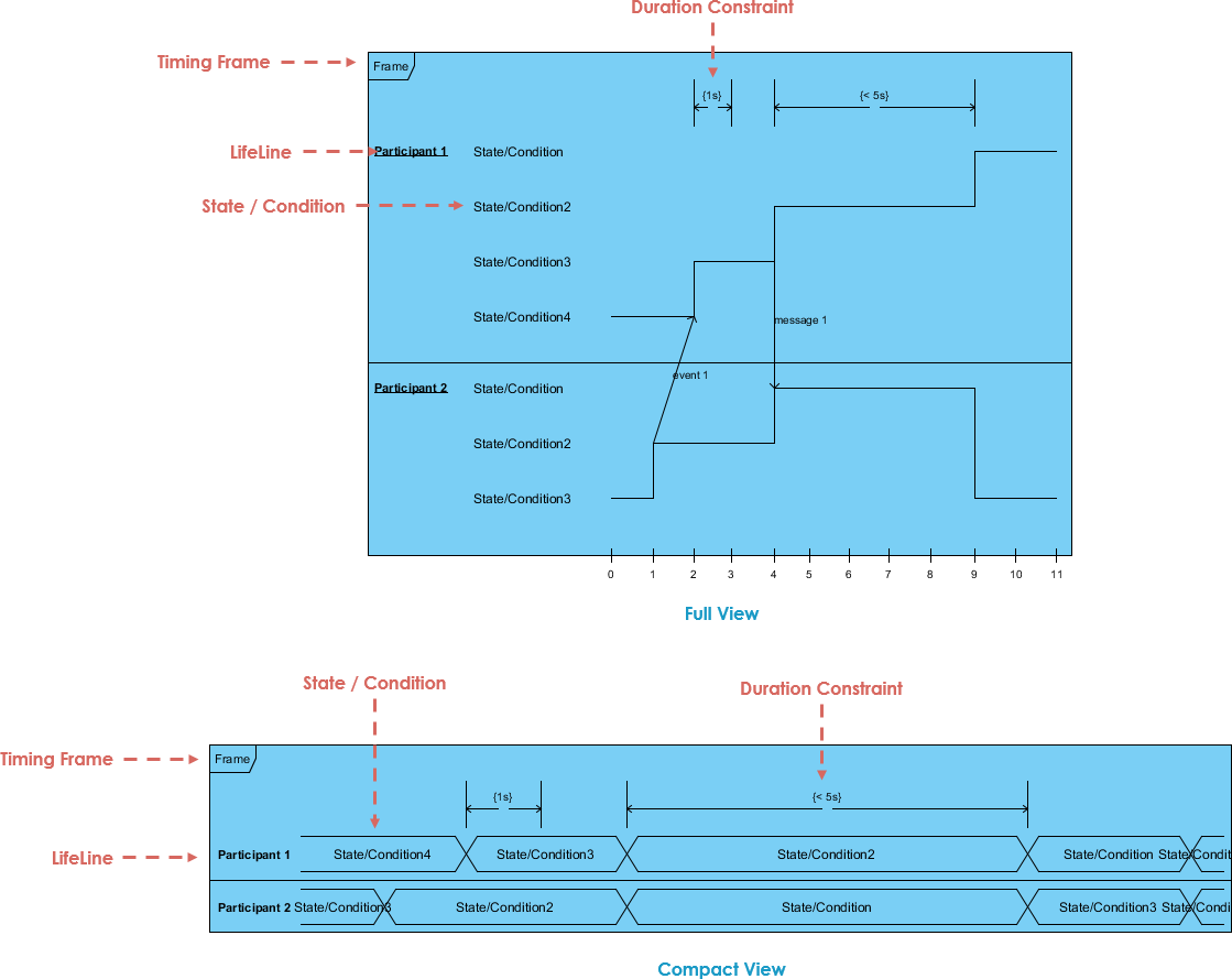
- Diagram Waktu – Diagram waktu berfokus terutama pada waktu, dan menggambarkan perubahan dalam pengklasifikasi pada garis waktu. Garis waktu ditumpuk secara vertikal, dengan waktu meningkat dari kiri ke kanan.
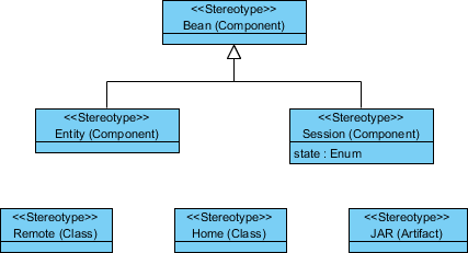
- Profil – Diagram Profil menggambarkan dan mendefinisikan ekstensi untuk bahasa UML. Mekanisme ekstensi memungkinkan Anda untuk menyesuaikan bahasa dengan domain atau platform tertentu. Ekstensi didefinisikan dengan stereotip.
Apa itu diagram kelas?
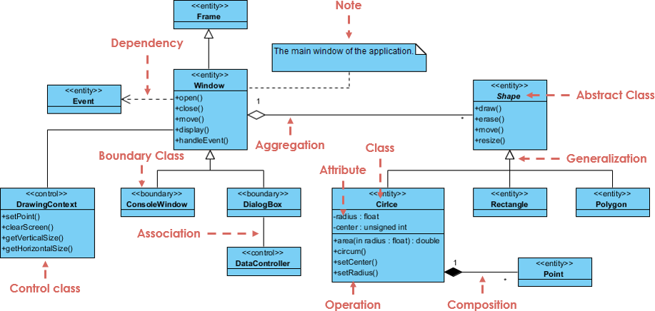
Diagram kelas adalah alat pemodelan inti dari semua metode berorientasi objek. Diagram kelas menggambarkan jenis objek dalam sistem dan berbagai hubungan statis yang ada di antara mereka. Ini digunakan untuk mewakili kelas, antarmuka, dan struktur serta hubungan statis di antara mereka.
- Generalisasi hubungan adalah hubungan pewarisan, yang menunjukkan bahwa subclass mewarisi semua fitur dan perilaku dari kelas induk. Sebuah garis solid dengan panah segitiga, panah menunjuk ke kelas induk.
- Realization hubungan adalah hubungan antara kelas dan antarmuka, yang menunjukkan bahwa kelas adalah implementasi dari semua fitur dan perilaku antarmuka.Sebuah garis putus-putus dengan panah segitiga, panah menunjuk ke antarmuka.
- Asosiasi hubungan adalah hubungan kepemilikan, yang memungkinkan satu kelas untuk mengetahui properti dan metode kelas lain.Sebuah garis solid dengan panah biasa menunjuk ke pemilik.Asosiasi dua arah dapat memiliki dua panah, atau tidak ada panah.Asosiasi unidirectional memiliki sebuah panah.
- Agregasi hubungan adalah hubungan antara keseluruhan dan bagian. Dan bagian dapat ada secara terpisah dari keseluruhan. Hubungan agregasi adalah sejenis hubungan asosiasi dan merupakan hubungan asosiasi yang kuat; asosiasi dan agregasi tidak dapat dibedakan secara gramatikal, dan hubungan logis spesifik harus diperiksa. Garis solid dengan berlian kosong, berlian kosong menunjuk ke keseluruhan.
- Komposisi hubungan adalah hubungan antara keseluruhan dan bagian. Tetapi bagian tidak dapat ada secara independen dari keseluruhan. Ini adalah sejenis hubungan asosiasi, yang lebih kuat daripada hubungan agregasi. Garis solid dengan berlian solid, yang menunjuk ke keseluruhan.
- Ketergantungan hubungan adalah hubungan penggunaan, yaitu, implementasi satu kelas memerlukan bantuan kelas lain. Ini adalah garis putus-putus dengan panah biasa, panah biasa menunjuk ke pengguna.
Apa itu diagram kasus penggunaan?
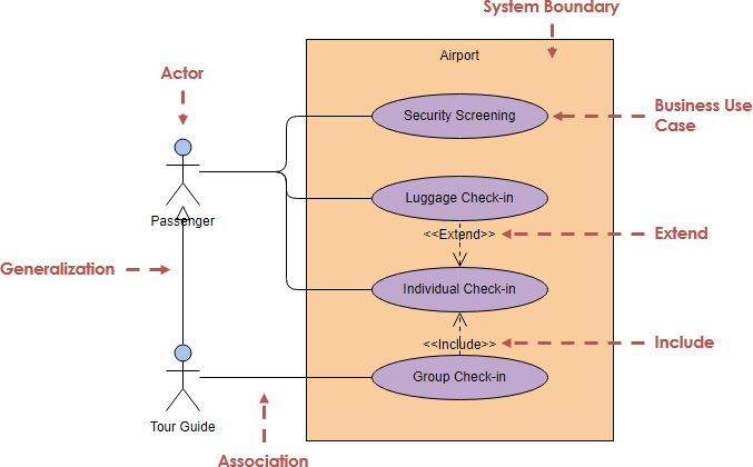
Diagram kasus penggunaan adalah pandangan yang menggambarkan fungsionalitas suatu sistem yang terdiri dari aktor, kasus penggunaan, batasan, dan hubungan mereka. Ini digunakan untuk menggambarkan fungsi dari seluruh sistem.
Diagram kasus penggunaan berisi tiga hubungan berikut:
- Hubungan include menggunakan simbol “include”. Jika Anda ingin melihat daftar pesanan, Anda perlu masuk terlebih dahulu.
- Hubungan ekstensi menggunakan simbol “extend”. Berdasarkan fungsi untuk menanyakan daftar pesanan, fungsi untuk mengekspor data dapat ditambahkan.
- Hubungan generalisasi, kasus penggunaan anak mewarisi semua struktur, perilaku, dan hubungan dari kasus penggunaan induk.
Apa itu diagram urutan?
- Diagram urutan menunjukkan bagaimana objek berkolaborasi sesuai dengan urutan waktu. Ini menunjukkan bagaimana objek berinteraksi dengan objek lain dalam skenario spesifik dari sebuah kasus penggunaan. Ini menunjukkan kolaborasi dinamis di antara beberapa objek dengan menggambarkan urutan waktu pesan yang dikirim antara objek.
Apa itu diagram aktivitas?
Diagram aktivitas menggambarkan proses implementasi dari kasus penggunaan bisnis tertentu. Ini digunakan untuk merepresentasikan alur kerja bisnis atau realisasi kasus penggunaan.
Apa itu Diagram Komunikasi?
Diagram komunikasi menggambarkan hubungan organisasi dari objek yang mengirim dan menerima pesan, menekankan hubungan kerjasama antara objek daripada urutan kronologis. Ini digunakan untuk menampilkan hubungan antara objek yang berbeda.
Apa itu diagram mesin keadaan?
Diagram mesin keadaan memodelkan perilaku dari sebuah objek tunggal, menunjukkan urutan di mana objek mengeksekusi peristiwa terkait sebagai respons terhadap peristiwa yang berbeda sepanjang siklus hidupnya. Ini digunakan untuk menunjukkan bahwa objek yang ditentukan merespons berbagai keadaan dari peristiwa yang berbeda sepanjang siklus hidupnya.
Apa itu diagram objek?
Diagram objek adalah sebuah contoh dari diagram kelas, sebuah snapshot dari keadaan detail sistem pada titik waktu tertentu. Ini digunakan untuk mengekspresikan hubungan antara dua atau lebih objek pada saat tertentu.
Apa itu diagram paket?
Diagram paket, sejenis diagram struktural, menunjukkan pengaturan dan organisasi elemen model dalam proyek skala menengah hingga besar. Ini digunakan untuk mengekspresikan ketergantungan antara paket dan paket.
Apa itu diagram komponen?
Diagram komponen menggambarkan antarmuka, port, dll. yang disediakan dan dibutuhkan oleh komponen dalam sistem, serta hubungan antara mereka. Ini digunakan untuk menampilkan ketergantungan antara komponen.
Apa itu diagram penyebaran?
Diagram penyebaran menggambarkan bagaimana perangkat lunak di dalam sistem didistribusikan di berbagai node. Ini digunakan untuk merepresentasikan hubungan pemetaan antara perangkat lunak dan perangkat keras.
Apa itu diagram struktur komposit?
Diagram Struktur Komposit menggambarkan struktur internal dari sebuah “struktur komposit” dan hubungan di antara mereka. “Struktur komposit” ini bisa menjadi bagian dari sistem, atau keseluruhan. Ini digunakan untuk merepresentasikan “struktur kombinasi” logis dalam sistem.
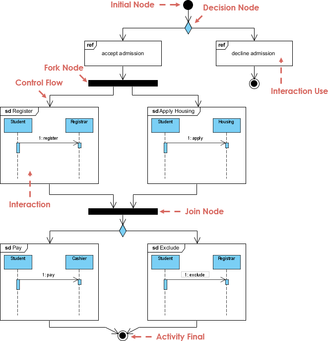
Apa itu diagram gambaran interaksi?
Diagram gambaran interaksi mirip dengan diagram aktivitas karena memberikan tingkat abstraksi tinggi untuk model interaksi. Ini adalah varian dari diagram aktivitas di mana node adalah interaksi atau situasi di mana interaksi terjadi. Ini fokus pada menggambarkan alur kontrol dari sebuah interaksi dan juga dapat menunjukkan alur aktivitas antara diagram.
Apa itu diagram waktu?
Diagram waktu digunakan untuk menunjukkan perubahan dalam nilai atau keadaan satu atau lebih elemen seiring waktu. Juga menunjukkan interaksi antara peristiwa yang terjadwal dan batasan waktu serta tenggat waktu yang mengaturnya.Sebuah tampilan yang digunakan untuk merepresentasikan keadaan atau nilai dari sebuah elemen yang berubah seiring waktu.
Apa itu Diagram Profil?
Diagram profil menyediakan mekanisme ekstensi generik untuk menyesuaikan model UML untuk domain dan platform tertentu.Ini digunakan untuk membangun model UML dalam domain tertentu.
UML itu Besar dan Kompleks?
UML benar-benar merupakan topik yang besar. UML menyediakan volume besar notasi diagram yang dikelompokkan menjadi 14 jenis diagram UML yang berbeda, masing-masing dengan model UML yang berbeda, melayani tujuan yang berbeda dan menangani aspek yang berbeda dari kebutuhan pengembangan.
- Setiap diagram UML dari 14 jenis diagram UML menyediakan seperangkat besar konstruksi dan notasi yang mencakup berbagai kebutuhan untuk sebagian besar proyek pengembangan perangkat lunak.
- Spesifikasi UML memiliki lebih dari 700 halaman, dan jelas dianggap terlalu kompleks dan memiliki dampak negatif pada persepsi dan adopsi UML.
- Biasanya, pengguna cenderung mempertimbangkan dan menggunakan hanya sebagian dari diagram/konstruksi UML.
Pelajari Diagram dan Notasi UML yang Paling Penting
Grady Booch, salah satu pengembang terpenting dari Unified Modeling Language, menyatakan bahwa “Untuk 80% dari semua perangkat lunak hanya 20% dari UML yang dibutuhkan.”
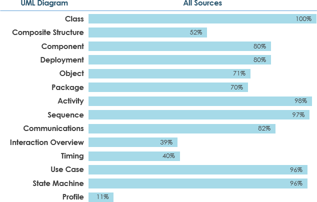
Apa yang Dinyatakan oleh Survei UML*?
Kita dapat menginterpretasikan hasil survei UML dengan mengasumsikan bahwa, jika sebuah diagram adalah
- digunakan secara luas, jika itu ≥ 60% dari sumber
- jarang digunakan jika itu ≤ 40% dari sumber
Buat Rencana Pembelajaran UML Anda
Berdasarkan angka yang dikumpulkan dalam survei, Anda dapat memiliki ide yang lebih baik tentang bagaimana memulai perjalanan pembelajaran UML Anda dengan mengembangkan rencana pembelajaran UML yang bermakna!
lebih
Sumber Daya Unified Modeling Language (UML):
- Apa itu UML?
- Mengapa Pemodelan UML?
- Ikhtisar dari 14 Jenis Diagram UML
- Apa itu Diagram Kolaborasi UML?
- Asosiasi UML vs Agregasi vs Komposisi
- Tutorial Diagram Kelas UML
- Bagaimana Memodelkan Pembatasan dalam UML?
- Diagram Mesin Keadaan vs Diagram Aktivitas
- Bagaimana Mengidentifikasi Aktor?
- Jenis Aktor dalam Model Kasus Penggunaan
- Apa itu Model-Tampilan dan Kontrol?
- Bagaimana Memodelkan Kerangka MVC dengan Diagram Urutan UML?
- UML – Diagram Perilaku vs Diagram Struktural
- Apa itu Mekanisme Ekstensibilitas UML?
- Panduan Praktis UML – Semua yang perlu Anda ketahui tentang pemodelan UML
- Pemodelan UML, Proses Perangkat Lunak dan Alat
- UML – Memodelkan Arsitektur Perangkat Lunak dengan Paket
- Semua yang Perlu Anda Ketahui tentang Diagram Keadaan
This post is also available in English, فارسی, Polski and Việt Nam.


