


Unified Modeling Language (UML) is a standard visual modeling language used to specify, visualize, construct, and document software systems. It provides a common vocabulary and notation for creating models that describe the structure and behavior of a system.
UML was created by the Object Management Group (OMG) and the first version, UML 1.0, was proposed in 1997. Since then, UML has become the industry standard for software modeling, and is widely used by developers, architects, and business analysts.
In this tutorial, we will explore the basics of UML and how it can be used to design and document software systems.
UML Building Blocks
UML consists of three main building blocks:
- Things: These are the basic elements of UML, such as classes, interfaces, use cases, and actors.
- Relationships: These describe how the things in a model are connected, such as associations, generalizations, and dependencies.
- Diagrams: These are visual representations of the system, created using the things and relationships. UML defines several types of diagrams, such as class diagrams, sequence diagrams, and use case diagrams.
Let’s explore these building blocks in more detail.
Things
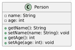
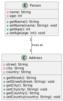
Classes: Classes represent the fundamental building blocks of an object-oriented system. They encapsulate data (attributes) and behavior (operations). Here’s an example of a Person class:
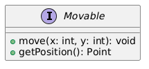
Interfaces: Interfaces define a contract that classes must implement. They specify a set of methods that a class must provide, without specifying the implementation details. Here’s an example of a Movable interface:
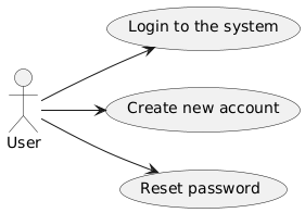
Use Cases: Use cases describe the interactions between a system and its users (actors). They capture the system’s functional requirements and describe how the system should behave in specific scenarios.
Relationships
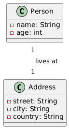
Associations: Associations represent relationships between classes. They can be bidirectional or unidirectional, and can have various multiplicities (one-to-one, one-to-many, many-to-many).
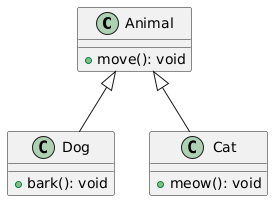
Generalizations: Generalizations represent inheritance relationships between classes. A subclass inherits the attributes and methods of its superclass.
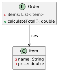
Dependencies: Dependencies represent the fact that one element (the client) relies on another element (the supplier) for its implementation or behavior.
Diagrams
UML defines several types of diagrams, each focusing on a different aspect of the system:
- Class Diagrams: Describe the structure of a system by showing its classes, their attributes, operations, and the relationships between them.
- Use Case Diagrams: Describe the functionality of a system by showing the actors, use cases, and their relationships.
- Sequence Diagrams: Describe the dynamic behavior of a system by showing the sequence of messages exchanged between objects.
- Activity Diagrams: Describe the flow of control in a system, focusing on the activities that are performed.
- State Machine Diagrams: Describe the dynamic behavior of a system by showing the different states an object can be in and the transitions between those states.
Here’s an example of a simple class diagram:
Conclusion
UML is a powerful tool for designing and documenting software systems. By understanding the basic building blocks of UML (things, relationships, and diagrams), you can create models that accurately represent the structure and behavior of your system. UML is an essential skill for any software developer or architect, and mastering it can greatly improve the quality and maintainability of your software projects.
This post is also available in Deutsch, Español, فارسی, Français, English, Bahasa Indonesia, 日本語, Polski, Portuguese, Ру́сский, Việt Nam, 简体中文 and 繁體中文.