


Unified Modeling Language (UML) Diagrams
Unified Modeling Language (UML) is a standard, general-purpose visual modeling language used in software engineering to depict the design of a system. It’s not a programming language but rather a visual language that helps in specifying, visualizing, constructing, and documenting the artifacts of software systems.
Why Use UML?
- Collaboration: Complex applications require clear communication among multiple teams. UML helps bridge the gap between technical and non-technical stakeholders.
- Understanding: Businessmen and system architects can understand essential requirements, functionalities, and processes of the system through UML.
- Time-saving: Visualizing processes and the static structure of the system helps save time and resources down the line.
Types of UML Diagrams
UML diagrams can be broadly classified into two categories: Structural and Behavioral.
1. Structural UML Diagrams
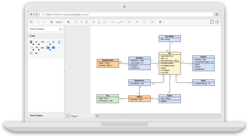
1.1. Class Diagram
- Depicts the static structure of a system using classes, their methods, and attributes.
- Helps identify relationships between different classes or objects.
- Visual Paradigm UML Tool: Class Diagram
1.2. Composite Structure Diagram
- Represents the internal structure of a class and its interaction points with other parts of the system.
- Similar to class diagrams but focuses on individual parts in detail.
- Visual Paradigm UML Tool: Composite Structure Diagram
1.3. Object Diagram
- Depicts specific instances of classes and relationships between them at a particular point in time.
- Similar to class diagrams but shows actual classifiers and their relationships.
- Visual Paradigm UML Tool: Object Diagram
1.4. Component Diagram
- Represents how physical components in a system are organized.
- Helps understand if functional requirements have been covered by planned development.
- Visual Paradigm UML Tool: Component Diagram
1.5. Deployment Diagram
- Represents system hardware and its software.
- Illustrates system architecture and the distribution of software artifacts over distributed targets.
- Visual Paradigm UML Tool: Deployment Diagram
1.6. Package Diagram
- Depicts how packages and their elements are organized.
- Shows dependencies between different packages and the internal composition of packages.
- Visual Paradigm UML Tool: Package Diagram
2. Behavioral UML Diagrams
2.1. State Machine Diagram
- Represents the dynamic behavior of a class in response to time and changing external stimuli.
- Models the condition of the system at finite instances of time using finite state transitions.
- Visual Paradigm UML Tool: State Machine Diagram
2.2. Activity Diagram
- Illustrates the flow of control in a system.
- Models sequential and concurrent activities, providing a visual representation of workflows.
- Visual Paradigm UML Tool: Activity Diagram
2.3. Use Case Diagram
- Depicts the functionality of a system or a part of a system.
- Illustrates functional requirements and the interaction of the system with external agents (actors).
- Visual Paradigm UML Tool: Use Case Diagram
2.4. Sequence Diagram
- Depicts interaction between objects in a sequential order.
- Describes how and in what order objects in a system function.
- Visual Paradigm UML Tool: Sequence Diagram
2.5. Communication Diagram
- Shows sequenced messages exchanged between objects.
- Focuses primarily on objects and their relationships.
- Visual Paradigm UML Tool: Communication Diagram
2.6. Timing Diagram
- A special form of Sequence diagram that depicts the behavior of objects over a time frame.
- Shows time and duration constraints that govern changes in states and behavior of objects.
- Visual Paradigm UML Tool: Timing Diagram
2.7. Interaction Overview Diagram
- Models a sequence of actions and simplifies complex interactions into simpler occurrences.
- A mixture of activity and sequence diagrams.
- Visual Paradigm UML Tool: Interaction Overview Diagram
Object-Oriented Concepts Used in UML Diagrams
- Class: Defines the structure and functions of an object.
- Objects: Help decompose large systems and modularize the system.
- Inheritance: Child classes inherit properties of parent classes.
- Abstraction: Emphasizes essential aspects of a system while disregarding irrelevant details.
- Encapsulation: Protects data from the outer world by binding it together.
- Polymorphism: Allows functions or entities to exist in different forms.
UML Diagrams Best Practices
- Understand your audience and tailor diagrams to their needs.
- Keep diagrams simple and focused on specific aspects of the system.
- Use consistent naming conventions and standard UML notations.
- Make relationships explicit with appropriate notations and labels.
- Balance Agile development and modeling to deliver value and maintain flexibility.
Steps to Create UML Diagrams
- Identify the purpose of the diagram.
- Identify key elements and relationships.
- Select the appropriate UML diagram type.
- Create a rough sketch.
- Choose a UML modeling tool (e.g., Visual Paradigm)).
- Create the diagram.
- Define element properties.
- Add annotations and comments.
- Validate and review.
- Refine and iterate.
Common Challenges and Benefits of UML Modeling
- Challenges: Time-intensive, over-documentation, changing requirements, collaboration issues.
- Benefits: Standardization, communication, visualization, documentation, analysis, and design.
UML and Agile Development
- UML diagrams serve as effective communication tools in Agile development.
- Use case diagrams can capture user stories and model user interactions.
- Iterative modeling in UML supports Agile’s iterative development approach.
- Balancing Agility and Modeling: Adaptive modeling, team empowerment, and valuing working software.
This post is also available in Deutsch, Español, فارسی, Français, English, Bahasa Indonesia, 日本語, Polski, Portuguese, Ру́сский, Việt Nam, 简体中文 and 繁體中文.