Czym jest diagram przypadków użycia?
UMLdiagramy przypadków użyciasą podstawową formą wymagań systemowych/programowych dla nowych programów komputerowych w trakcie rozwoju. Celem diagramu przypadków użycia jest zobrazowanie tego, co system powinien robić (co); na tym etapie nie bierze się pod uwagę, jak (jak) to zrobić.
Gdy przypadek użycia jest określony, może być przedstawiony w formie tekstowej i wizualnej (tj. diagramu przypadków). Kluczowym pojęciem modelowania przypadków użycia jest to, że pomaga nam zaprojektować system z perspektywy końcowego użytkownika. Jest to skuteczna technika komunikacji zachowań systemu w terminach użytkownika poprzez określenie wszystkich zewnętrznie widocznych zachowań systemu.
Innymi słowy, korzystanie z systemu musi być postrzegane z zewnątrz, to znaczy, system nie powinien być postrzegany od wewnątrz, ale z wyższego poziomu, aby określić funkcjonalność, którą system powinien zapewnić zewnętrznym aktorom.
Cel diagramów przypadków użycia
Diagramy przypadków użyciasą zazwyczaj opracowywane w wczesnych etapach rozwoju, a ludzie często wykorzystują modelowanie przypadków użycia do następujących celów.
- Określenie kontekstu systemu
- Zbieranie wymagań systemu
- Walidacja architektury systemu
- Napędzanie wdrożenia i generowanie przypadków testowych
- Opracowywanie przez analityków, ekspertów dziedzinowych i docelowych użytkowników końcowych wspólnie
Standardowa forma diagramu przypadków użycia jest zdefiniowana w Zjednoczonym Języku Modelowania, jak pokazano w poniższym przykładzie diagramu przypadków użycia.
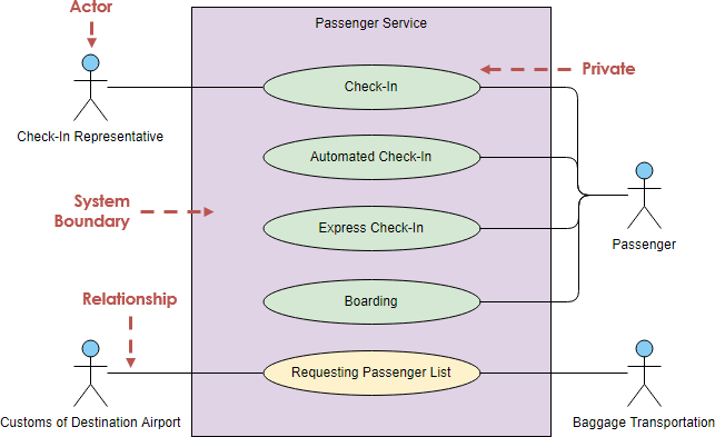
Edytuj ten przykład diagramu przypadków użycia
Elementy diagramu przypadków użycia
Aktorzy
Każdy przypadek użycia będzie miał co najmniej jednego aktora, który może być rozumiany jako co najmniej jeden uczestnik (rola), który niekoniecznie musi być osobą, ale może być innym systemem lub urządzeniem. Aktor może wchodzić w interakcje z więcej niż jednym przypadkiem użycia, a przypadek użycia może wchodzić w interakcje z więcej niż jednym aktorem.
Aktorzy nie są koniecznie ludźmi, tj. użytkownikami, ale mogą być rzeczywiście nie-ludźmi, tj. systemami lub czasem.
Najczęściej użytkownikami są ludzie, którzy są zaangażowani w diagram przypadków użycia, tacy jak klienci, pracownicy, przełożeni itp.
Aktorzy ludzcy vs nie-ludzcy
Od czasu do czasu system jest wpływany przez różne zdarzenia, aby wykonać określone funkcje w danej sytuacji. Na przykład, gdy audyt jest zakończony, system proaktywnie wysyła list, aby powiadomić ludzi; czy więc wysyłanie listu jest wykonywane automatycznie przez system? Ten przypadek użycia jest w rzeczywistości wyzwalany przez czas, wtedy aktorem jest Timer; na przykład, ten przypadek użycia można postrzegać jako „automatyczne wysyłanie listu o 5:00 każdego dnia”, wtedy aktorem, który wyzwala to zdarzenie – wysyłanie listu – nie jest system, ale w rzeczywistości aktor Timer.
Aktorzy główni vs pomocniczy
Aktor główny to aktor, który korzysta z systemu, aby osiągnąć cel. Przypadki użycia dokumentują interakcje między systemem a aktorami w celu osiągnięcia celów aktora głównego. Aktorzy pomocniczy to aktorzy, których system potrzebuje, aby pomóc w osiągnięciu celów aktora głównego.
- Aktorzy mogą być główni lub pomocniczy. Aktorzy główni inicjują interakcje z systemem.
- Aktorzy pomocniczy są zazwyczaj wzywani przez system do pomocy, a aktor pomocniczy nigdy nie inicjuje przypadku użycia.
Zauważ, że: symbol aktora nie różnicuje między aktorem głównym a aktorem pomocniczym; różnicę należy wywnioskować z opisów przypadków użycia (zwanych również narracjami przypadków użycia).
Na przykład:
Pracownik banku zajmujący się pożyczkami chce przejrzeć wniosek o pożyczkę klienta, a część procesu obejmuje sprawdzenie oceny kredytowej w czasie rzeczywistym.
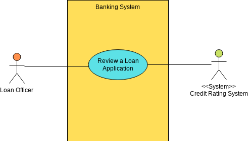
Edytuj ten przykład diagramu przypadków użycia
- Nazwa przypadku użycia. Przegląd wniosku o pożyczkę
- Aktor główny. Pracownik banku
- Aktor pomocniczy. System oceny kredytowej
Jak zidentyfikować aktorów?
Ponieważ aktor niekoniecznie musi być osobą, ale może być zewnętrznym systemem, urządzeniem lub timerem, znajdujemy bardziej specyficznego aktora, zadając następujące pytania
- Kto będzie korzystał z systemu po jego opracowaniu?
- Od kogo lub z jakich innych systemów system będzie musiał uzyskać dane?
- Dla kogo lub jakich innych systemów system będzie dostarczał dane?
- Z jakimi innymi systemami system będzie powiązany?
- Kto będzie utrzymywał i zarządzał systemem?
Te pytania pomagają nam abstrahować aktorów systemu. Używając bankomatów jako przykładu, odpowiadając na te pytania, możemy znaleźć więcej aktorów, tj.
- Operatoroperatorjest odpowiedzialny za utrzymanie i zarządzanie systemem bankomatów
- Bankomaty muszą również komunikować się zserwerami zapleczaaby uzyskać informacje o kontach użytkowników.
Przypadek użycia
Przypadek użycia reprezentuje funkcjonalność (zwykle wymaganie), która ma być wdrożona przez system. Szczegóły przypadku użycia, poza jego unikalną nazwą, nie są przedstawiane wizualnie w diagramie; te szczegóły są podane w narracji (opisie tekstowym) przypadku użycia.
Przypadek użycia to lista działań lub kroków zdarzeń, które zazwyczaj definiują interakcje między rolami aktorów a systemem w celu osiągnięcia celu. Przypadki użycia są użyteczną techniką do identyfikacji, wyjaśniania i organizowania wymagań systemowych. Przypadek użycia składa się z zestawu sekwencji możliwych interakcji między systemem a użytkownikiem, które definiują funkcjonalność do osiągnięcia oraz rozwiązania wszelkich błędów, które mogą wystąpić.
Jak zidentyfikować przypadki użycia?
Gdy znajdziemy aktorów, możemy określić przypadki użycia systemu na podstawie aktorów, głównie patrząc na to, jakie usługi każdy aktor potrzebuje od systemu lub jak aktorzy korzystają z systemu. Identyfikacja przypadków użycia może rozpocząć się od następujących pytań (dla każdego uczestnika).
- Dlaczego aktorzy korzystają z systemu?
- Czy uczestnik tworzy, modyfikuje, usuwa, uzyskuje dostęp i przechowuje dane w systemie? Jeśli tak, jak aktor wykonuje te operacje?
- Czy aktor powiadamia system o pewnych zdarzeniach zewnętrznych?
- Czy system powiadamia aktora o pewnych zdarzeniach wewnętrznych?
Łącząc powyższe, diagram przypadków użycia systemu bankomatów może być przedstawiony w następujący sposób.
Przypadek użycia jest przedstawiany przez elipsy, coś statycznego lub dynamicznego, lub zadanie lub system.
Granica systemu
Granice systemu opisują system, grupując przypadki użycia w prostokątnych granicach, a granice systemu w Visual Paradigm zapewniają zachowanie zawierania przypadków użycia.
Aktorzy to role (aktorzy ludzcy lub nie-ludzcy), które wchodzą w interakcje z rozwijanym systemem. Dlatego aktorzy powinni być umieszczani poza granicami systemu i wchodzić w interakcje z przypadkami użycia, które są umieszczone w granicach systemu.
Zauważ, że:
Aktor jest definiowany przez granice systemu. Jeśli granica systemu, którą chcemy zdefiniować, ogranicza się do samego bankomatu, to serwer zaplecza jest systemem zewnętrznym i może być abstrahowany jako aktor.
Jeśli granica systemu, którą chcemy zdefiniować, rozciąga się na cały system bankowy, w którym zarówno bankomaty, jak i serwery zaplecza są częścią całego systemu bankowego, to serwer zaplecza nie jest już abstrahowany jako aktor.
Relacja
Po zapoznaniu się z tymi trzema kluczowymi symbolami, kontynuuj wiedzę o relacjach i rysowaniu diagramów przypadków użycia. Bezpośrednia relacja między uczestnikiem a przypadkiem użycia jest rysowana, a relacja jest przedstawiana jako linia bez strzałek, wskazująca na relację dwukierunkową, zwaną linią łączącą.
Przypadek użycia może być podzielony na kilka przypadków użycia, które są połączone relacjami <<include>>, <<extend>> lub <<generalization>> (opisanymi później w tym poście).
Relacja łączności komunikacyjnej
Reprezentuje to dwukierunkową komunikację między aktorem a przypadkiem użycia, a zatem jest to relacja binarna.

Edytuj ten przykład diagramu przypadków użycia
Relacja <<Include>>
Relacja includerelacja oznacza, że przypadek użycia będzie zawierał inne przypadki użycia. Celem relacji Include jest użycie relacji Include, aby zredukować powtarzalność opisywania tego samego przypadku użycia ponownie. Jeśli wiele przypadków dzieli tę samą funkcję, to funkcja może być wydzielona, a inne przypadki użycia mogą być włączone do tego przypadku.
Na przykład, bibliotekarz musi odczytać kod, aby zarejestrować wypożyczoną książkę, gdy książka jest wypożyczana, a także musi odczytać kod, aby zarejestrować zwróconą książkę, gdy książka jest zwracana, ponieważ odczytanie kodu jest powtarzalną częścią działania, można to przekształcić w osobny przypadek użycia i pozwolić, aby wypożyczona książka i zwrócona książka zawierały ten przypadek.
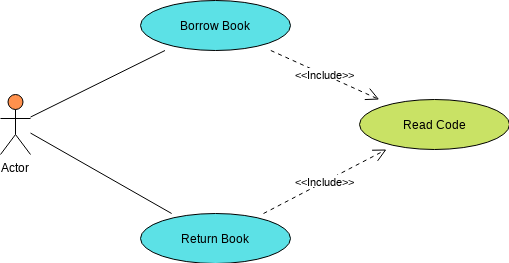
Edytuj ten przykład diagramu przypadków użycia
Jeśli przypadek użycia A zawiera inny przypadek użycia B, to wdrożenie A wymaga wdrożenia B, aby zakończyć swoje zadanie. Jednak B jest niezależne od siebie. To znaczy, że B nie musi wiedzieć nic o A. B może być również zawarte w dowolnym innym przypadku użycia.
Relacja <<Extend>>
Jeśli przypadek użycia B rozszerza inny przypadek użycia A, to wdrożenie A może warunkowo zawierać wdrożenie B, aby zakończyć swoje zadanie. To znaczy, że w niektórych przypadkach A może zakończyć swoje zadanie bez B. Jednak w zależności od opisanych warunków A może wymagać B. W tym przypadku B jest zależne od A. Jednak w zależności od opisanych warunków A może wymagać B. W tym przypadku B jest zależne od A i nie może istnieć samodzielnie. Z tego powodu B nie może być rozszerzane na więcej niż jeden przypadek użycia. Narracja przypadku użycia A będzie zawierać kroki wykonania, które wymaga od B; ten punkt nazywa się punktem rozszerzenia.

Edytuj ten przykład diagramu przypadków użycia
Przyjrzyjmy się innemu przykładzie, w którym system automatycznie zamawia towary, gdy nie ma zapasów, aby menedżer nie musiał bezpośrednio realizować zamówienia. Zobacz diagram przypadków użycia poniżej:
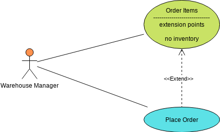
Edytuj ten przykład diagramu przypadków użycia
Relacja generalizacji
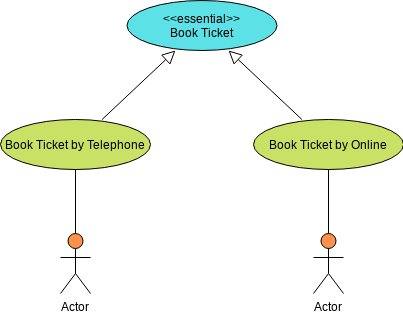
Relacja generalizacji jest podobna do relacji generalizacji w języku obiektowym w diagramach klas i może być stosowana do generalizacji ról (aktorów) i przypadków użycia.
Na przykład w systemie rezerwacji istnieją dwa rodzaje metod rezerwacji: „rezerwacja biletu przez telefon” i „rezerwacja biletu online”, a podstawowy przypadek użycia to „rezerwacja biletu”, więc można użyć generalizacji, aby uformować przypadek i dodać <<istotne>> do nadrzędnego przypadku użycia (rezerwacja), aby wskazać relację generalizacji.
Edytuj ten przykład diagramu przypadków użycia
Omów relacje w diagramie przypadków użycia
- W ogólnym diagramie przypadków użycia przedstawiamy tylko relacje między aktorami a przypadkami użycia, tj. powiązania komunikacyjne między nimi.
- Ponadto możemy również opisać generalizację między uczestnikami a aktorami oraz relacje include, extend i generalization między przypadkami użycia.
- Używamy tych relacji, aby dostosować istniejący model przypadków użycia i wydobyć wspólne informacje do ponownego wykorzystania, co ułatwia utrzymanie modelu przypadków użycia.
- Jednak musimy być ostrożni przy wyborze tych relacji w aplikacji. Zazwyczaj te relacje zwiększają liczbę przypadków użycia i relacji, co zwiększa złożoność modelu przypadków użycia.
- Ponadto model przypadków użycia jest zazwyczaj dostosowywany po jego ukończeniu, więc nie ma potrzeby spieszyć się z abstrahowaniem relacji między przypadkami użycia na wczesnym etapie modelowania przypadków użycia.
Przypadek użycia – przepływ zdarzeń
Diagram przypadków użycia daje nam ogólny widok funkcjonalności systemu, możemy wiedzieć, którzy uczestnicy będą wchodzić w interakcje z systemem i jakie usługi każdy aktor potrzebuje uzyskać od systemu.
Przypadek użycia opisuje rozmowę między aktorami a systemem, ale szczegóły tej rozmowy nie są przedstawione w diagramie przypadków użycia, więc dla każdego przypadku użycia możemy opisać szczegóły tej rozmowy w postaci strumienia zdarzeń.
Scenariusze przypadków użycia i przepływ zdarzeń – Wypłata pieniędzy z bankomatu
Na przykład przypadek „Wypłata” w systemie bankomatów może być przedstawiony jako przepływ zdarzeń w następujący sposób:
Normalny scenariusz – Wypłata środków – podstawowy przebieg zdarzeń:
- Użytkownik wkłada kartę kredytową
- Wprowadź PIN
- Wprowadź kwotę wypłaty
- Wypłaca gotówkę
- Wyjdź z systemu i odbierz kartę kredytową
Ale to tylko opisuje normalny scenariusz przypadku użycia wypłaty. Jako prawdziwy system bankomatu musimy również rozważyć różne inne scenariusze, które mogą wystąpić, takie jak:
- nieważne karty kredytowe,
- błędne hasła,
- niewystarczający stan gotówki na koncie użytkownika, itd.
Wszystkie te możliwe sytuacje (zarówno normalne, jak i nienormalne) nazywane są scenariuszami przypadku użycia, a scenariusze są również nazywane instancjami przypadku użycia. Scenariusze są również określane jako instancje przypadków użycia. Wśród różnych scenariuszy przypadku użycia, najczęstszy scenariusz jest opisany przez podstawowy proces, podczas gdy inne scenariusze są opisane przez alternatywne procesy.
Scenariusze alternatywne
Dla przypadku użycia „Wypłata” w systemie bankomatu możemy uzyskać następujące alternatywne procesy.
Wypłata – alternatywne procesy zdarzeń.
- Scenariusz alternatywny I: Użytkownik może zrezygnować na dowolnym etapie podstawowego procesu i przejść do kroku 5 podstawowego procesu.
- Alternatywny proces II: W kroku 1 podstawowego procesu użytkownik wkłada nieważną kartę kredytową, system wyświetla błąd i zwraca kartę kredytową, a przypadek użycia kończy się.
- Alternatywny proces III: W kroku 2 podstawowego procesu użytkownik wprowadza niepoprawne hasło, system wyświetla błąd i prosi użytkownika o ponowne wprowadzenie hasła oraz powrót do kroku 2 podstawowego procesu; po trzech niepoprawnych próbach wprowadzenia hasła karta kredytowa jest konfiskowana przez system, a przypadek użycia kończy się.
- …
Łącząc podstawowy scenariusz i scenariusze alternatywne, można wyraźnie opisać wszystkie różne sytuacje, które mogą wystąpić w przypadku użycia. Opisując przebieg zdarzeń przypadku użycia, chcemy jak najlepiej opisać wszystkie możliwe scenariusze, aby zapewnić kompletność wymagań.
Model przypadku użycia a diagramy przypadków użycia
Ważne jest, aby unikać błędnego przekonania, że diagram przypadku użycia składający się z aktorów i przypadków użycia jest modelem przypadku użycia, ponieważ diagram przypadku użycia jest tylko wizualną reprezentacją usług, które system może świadczyć, dając nam ogólny obraz funkcjonalności systemu.
Model przypadku użycia składa się z diagramu przypadku użycia oraz szczegółowego opisu każdego przypadku użycia, specyfikacji przypadku użycia, która jest dostarczana jako szablon w RUP.
Krótki opis
Krótki opis roli i celu przypadku użycia.
Przebieg zdarzeń
Przebieg zdarzeń powinien reprezentować wszystkie scenariusze, w tym podstawowe i alternatywne scenariusze.
Scenariusze przypadków użycia
Zawierają scenariusze sukcesu i scenariusze niepowodzenia, a scenariusze są głównie kombinacją podstawowych i alternatywnych przepływów.
Wymagania specjalne
Opisz wymagania niefunkcjonalne (w tym wydajność, niezawodność, dostępność, skalowalność itp.) oraz ograniczenia projektowe (system operacyjny, narzędzia programistyczne itp.) związane z przypadkiem użycia.
Warunek wstępny
Stan, w którym system musi się znajdować przed wykonaniem przypadku użycia.
Warunki końcowe
Zbiór stanów, w których system może się znajdować po wykonaniu przypadku użycia.
Specyfikacja przypadku użycia jest zasadniczo reprezentacją tekstową, z możliwością użycia diagramów stanów, diagramów aktywności lub diagramów sekwencji, aby pomóc w jaśniejszym opisaniu przebiegu zdarzeń. Każda graficzna reprezentacja interfejsów użytkownika i procesów, lub inne grafiki, tj. makiety, mogą być dołączone do przypadku użycia, o ile pomagają poprawić klarowność reprezentacji.
Na przykład:
- diagramy aktywności są przydatne do opisywania złożonych procesów decyzyjnych,
- diagramy przejść stanów są przydatne do opisywania zachowań systemu związanych ze stanem, a
- diagramy sekwencji są odpowiednie do opisywania komunikacji opartej na czasie.
Narzędzia do przypadków użycia
Wersja online
Darmowe narzędzie do rysowania Visual Paradigm Online (VP Online) darmowa wersja wspiera UML, ERD i diagramy organizacyjne. Możesz szybko rysować diagramy przypadków użycia za pomocą intuicyjnego edytora rysunków UML. To darmowe narzędzie UML nie ma reklam, nie ma ograniczonego okresu dostępu i nie ma ograniczeń, takich jak liczba diagramów, liczba kształtów itp. Rysuj UML swobodnie. Rysuj UML swobodnie. Posiadasz diagramy, które tworzysz do celów osobistych i niekomercyjnych.
Wersja desktopowa
Model Visual Paradigm Community Edition, dostępna od 2004 roku, oferuje darmowe oprogramowanie UML tylko do celów niekomercyjnych, wspierając użytkowników, którzy stawiają pierwsze kroki w modelowaniu UML, a także tych, którzy potrzebują darmowego, wieloplatformowego oprogramowania do modelowania UML do użytku osobistego, takiego jak stosowanie UML w projektach studenckich.
Bibliografia
- Czym jest diagram przypadku użycia?
- Rodzaje aktorów w modelu przypadku użycia
- Identyfikacja wymagań użytkowników za pomocą diagramów przypadków użycia
- Czym jest specyfikacja przypadku użycia?
- Historia użytkownika a przypadek użycia w zwinnej metodzie wytwarzania oprogramowania
- Podejście oparte na przypadkach użycia w zwinnej metodzie wytwarzania
Zasoby UML
Ten post dostępny jest również w Deutsch, English, Español, فارسی, Français, Bahasa Indonesia, 日本語, Portuguese, Ру́сский, Việt Nam, 简体中文 and 繁體中文


