Przypadki użycia modelują widoki użytkowników na funkcje systemu, to znaczy,
- co system robi z perspektywy użytkownika;
- To, co robi, jest cenne dla użytkownika.
- Model przypadków użycia zapewnia sposób organizacji, strukturyzacji i dokumentowania dużej ilości informacji zebranych podczas pozyskiwania wymagań;
- Stanowi integralną część fazy opisu wymagań w procesie rozwoju.
Przypadki użycia są często graficzne, a diagramy przypadków użycia są wspierane przez opisy tekstowe, w tym opisy przypadków użycia i uczestników, a także scenariusze związane z szablonami przypadków użycia, które sprawiają, że metody przypadków użycia są proste i intuicyjne oraz idealnymi narzędziami do omawiania i wyjaśniania zrozumienia potrzeb użytkowników przez programistów.
Gdy model przypadków użycia zostanie ukończony i omówiony z użytkownikiem, stanowi podstawowy, uporządkowany zbiór informacji, na podstawie którego będą tworzone inne modele systemu. Model przypadków użycia jest również przydatny do testowania funkcjonalności systemu.
Model Przypadków Użycia
Model przypadków użycia składa się z:
- diagramu przypadków użycia,
- zestawu opisów przypadków użycia,
- zestawu opisów aktorów
- zestawu scenariuszy (opisanego przez przebieg zdarzeń).
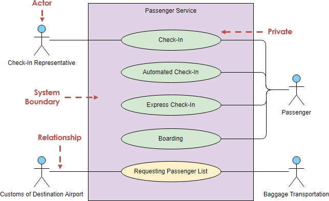
Diagram przypadków użycia wykorzystuje cztery pojęcia do graficznego modelowania obszaru problemowego: przypadek użycia, aktor, link relacji i granicę.
Przypadek użycia: elipsa oznaczona nazwą przypadku użycia. Zgodnie z konwencją, każdą nazwę przypadku użycia zaczynamy od czasownika, aby wskazać, że przypadek użycia reprezentuje proces. Dlatego używamy „utrzymanie listy klientów” zamiast „lista klientów”, oraz „przetwarzanie zapytania” zamiast „zapytanie”.
Aktor: prosty rysunek postaci z imieniem aktora. Piszemy imię aktora wielką literą dla łatwej identyfikacji (np. Bibliotekarz, Student).
Aktorzy mogą byćludźmi, innymi systemami, wyzwalaczami czasowymi lub wyzwalaczami zdarzeń. Aktor określa rolę odgrywaną przez użytkownika lub inny system, który wchodzi w interakcję z tematem. Może reprezentować role odgrywane przez użytkowników ludzkich, zewnętrzny sprzęt lub inne podmioty.
Relacja przypadków użycia: linia łącząca aktorów z przypadkami użycia. Ta linia pokazuje, którzy aktorzy są powiązani z którymi przypadkami użycia. Ta relacja nazywana jest również komunikacją.
Granice: Prostokąt narysowany wokół przypadków użycia, który oddziela je od aktorów w celu opisania zakresu systemu. Granice systemu są opcjonalne i często ignorowane.

Cel diagramu przypadków użycia
Modelowanie przypadków użycia odbywa się na różnych etapach procesu rozwoju oprogramowania obiektowego. Poziom szczegółowości i rodzaj informacji wyświetlanych w każdej fazie zależy od celu modelu. Informacje związane z szczegółowym projektem lub wdrożeniem systemu nie są uwzględniane we wczesnych etapach, gdy głównym celem jest komunikacja z użytkownikami. Później dodawane będą szczegóły techniczne, takie jak projektowanie interfejsu użytkownika, dla odniesienia programistów.
Przypadek użycia vs Diagram klas w rozwoju systemu
Ważne jest, aby zrozumieć, że chociaż model przypadków użycia dzieli i strukturyzuje wymagania systemowe, ta struktura nie jest używana jako podstawa do budowy nowych systemów oprogramowania, co w rzeczywistości zapewniają diagramy klas.
Model przypadków użycia konstruuje system jako główny widok zadań użytkownika.
Diagramy klas konstruują systemy, wykorzystując zestaw logicznych komponentów oprogramowania (obiektów).
Diagramy UML
- Czym jest UML?
- Dlaczego modelowanie UML?
- Przegląd 14 typów diagramów UML
- Czym jest diagram klas?
- Czym jest diagram komponentów?
- Czym jest diagram wdrożenia?
- Czym jest diagram obiektów?
- Czym jest diagram pakietów?
- Czym jest diagram struktury złożonej?
- Czym jest diagram profilu?
- Czym jest diagram przypadków użycia?
- Czym jest diagram aktywności?
- Czym jest diagram maszyny stanowej?
- Czym jest diagram sekwencji?
- Czym jest diagram komunikacji?
- Czym jest diagram przeglądu interakcji?
- Czym jest diagram czasowy
Ten post dostępny jest również w Deutsch, English, Español, فارسی, Français, Bahasa Indonesia, 日本語, Portuguese, Ру́сский, Việt Nam, 简体中文 and 繁體中文


