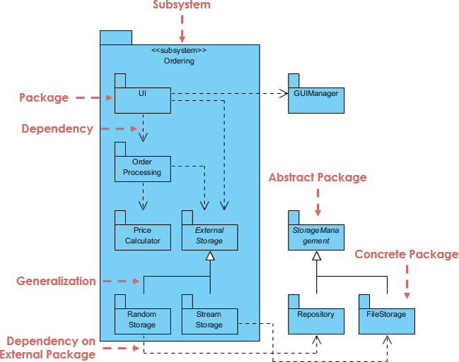
A UML Package Diagram is used to organize and group parts of a system into packages, making it easier to manage complex systems. Packages can contain classes, interfaces, sub-packages, and other UML elements. In this tutorial, we will walk through how to interpret and create a UML Package Diagram based on the provided diagram.

1. Understanding the Elements of the Provided UML Package Diagram
The provided diagram contains several key features typical of a UML package diagram. Let’s break them down:
a. Packages
- Packages are represented by rectangles with tabs at the top. They are containers that group related elements (like classes or sub-packages).
- In the diagram:
- Ordering (subsystem) is a package that contains several classes or components, such as
UI,Order Processing,Price Calculator, andExternal Storage. - Storage Management is an abstract package, containing
RepositoryandFileStorageclasses. - External Storage (inside the Ordering package) has generalization relationships with
Random StorageandStream Storage.
- Ordering (subsystem) is a package that contains several classes or components, such as
b. Subsystem
- A Subsystem is a higher-level abstraction that groups sets of functionalities. In the diagram, the
Orderingpackage is marked as a subsystem (<<subsystem>>), representing a specific module in the system.
c. Dependencies
- Dependencies indicate that one package or class depends on another. This is represented by dashed arrows.
- In the diagram:
- The
Order Processingclass has a dependency on theExternal Storagepackage. - The
Orderingsubsystem depends on theGUImanagerclass.
- The
d. Generalization
- Generalization relationships indicate inheritance or implementation between classes or packages. This is represented by a solid line with a triangle at one end.
- In the diagram:
External Storageis a generalization ofRandom StorageandStream Storage, meaning these two classes inherit fromExternal Storage.
e. Abstract Package
- The
Storage Managementpackage is abstract, which is indicated by the italicized name of the package. It typically means that the package contains abstract elements that cannot be instantiated directly.
f. Concrete Package
- A Concrete Package contains real entities or classes that can be instantiated. In the diagram,
RepositoryandFileStorageare concrete packages underStorage Management.
g. External Packages
- The
GUImanageris an external package/component that is outside theOrderingsubsystem but has a dependency relationship with it. This is shown by the dashed arrow pointing fromUItoGUImanager.
2. Step-by-Step Guide to Creating a UML Package Diagram Using Visual Paradigm
Step 1: Open Visual Paradigm
- Launch Visual Paradigm and create a new project.
- Select Diagram from the toolbar and choose Package Diagram from the list of UML diagrams.
Step 2: Add a Main Subsystem (Package)
- Use the Package tool from the toolbox to create a package.
- Name the package
Orderingand add the stereotype<<subsystem>>to show that it’s a subsystem.
Step 3: Add Classes Inside the Package
- Inside the
Orderingpackage, add the following elements:UIOrder ProcessingPrice CalculatorExternal Storage(which will later have subclasses)
- You can do this by dragging the Class tool inside the package area and naming the classes accordingly.
Step 4: Create Dependencies
- Use the Dependency tool (dashed arrow) to establish the following relationships:
- From
Order ProcessingtoExternal Storage - From
UItoGUImanager(External Package)
- From
Step 5: Add Generalization Relationships
- Under the
External Storageclass, add two more classes:Random StorageandStream Storage. - Use the Generalization tool (solid line with a triangle) to connect
Random StorageandStream StoragetoExternal Storage, indicating inheritance.
Step 6: Add the Abstract Package
- Create the
Storage Managementpackage outside of theOrderingsubsystem. - Mark it as abstract by italicizing the name or adding a note indicating that it’s abstract.
- Inside
Storage Management, addRepositoryandFileStorageas concrete classes/packages.
Step 7: Establish External Dependencies
- Use the Dependency tool again to show the relationship between
Orderingand the externalGUImanagerpackage.
Step 8: Finalize the Diagram
- Make sure all relationships are correctly represented:
- Dependencies are shown with dashed lines.
- Generalizations are shown with solid lines and triangles.
- External packages and classes are clearly indicated.
3. Key Points to Remember
- Packages are used to group related elements, helping to manage the complexity of a large system.
- Dependencies show that one package or class relies on another.
- Generalization shows inheritance or implementation relationships.
- Subsystems are higher-order packages that represent a particular module in the system.
- Abstract Packages cannot be instantiated directly, while Concrete Packages can.
- External Packages are outside the main subsystem but can still interact with elements inside it.
4. Conclusion
This tutorial has walked you through the steps to create a UML Package Diagram using Visual Paradigm, based on the provided diagram. Package diagrams are essential for organizing large systems, especially when different subsystems or modules interact with one another. By using Visual Paradigm, you can easily create and manage these diagrams, making your system architecture more understandable and maintainable.
Official Visual Paradigm Resources
- Visual Paradigm UML Tutorial
https://www.visual-paradigm.com/tutorials/uml-tutorial/
This is the official UML tutorial page for Visual Paradigm, covering various types of UML diagrams, including package diagrams. - What is a UML Package Diagram?
https://www.visual-paradigm.com/guide/uml-unified-modeling-language/what-is-package-diagram/
A dedicated article explaining UML Package Diagrams, including examples and step-by-step guides on creating them using Visual Paradigm. - UML Tool Guide
https://www.visual-paradigm.com/guide/uml-unified-modeling-language/
This guide provides an overview of UML diagrams and tools available in Visual Paradigm.

