Introduction to UML
Unified Modeling Language (UML) is a standardized modeling language consisting of an integrated set of diagrams, developed to help system and software developers for specifying, visualizing, constructing, and documenting the artifacts of software systems. UML is widely used in the software industry for designing the structure and behavior of systems.
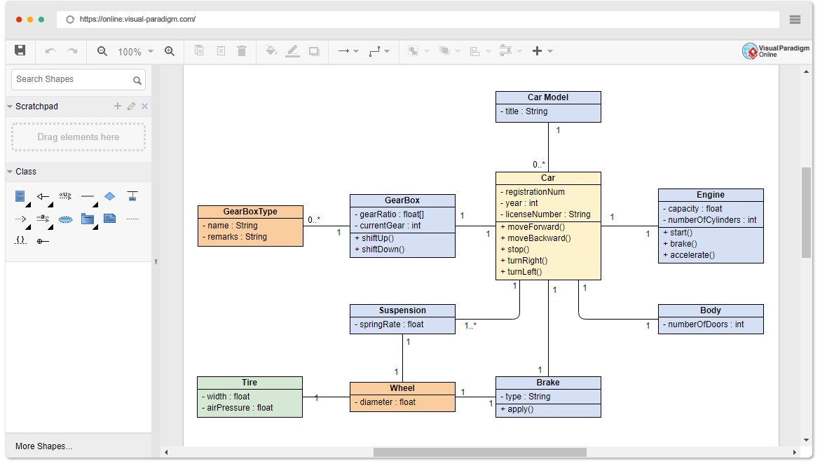
Why Use UML?
Unified Modeling Language (UML) is a standardized modeling language that provides a visual way to specify, construct, and document the artifacts of a software system. Here are some key reasons why developers and organizations use UML:
- Communication: UML diagrams serve as a common language for stakeholders, including developers, designers, project managers, and clients. They help bridge the gap between technical and non-technical team members.
- Design and Planning: UML aids in the design and planning phases of software development by providing a clear visual representation of the system’s architecture, components, and interactions.
- Documentation: UML diagrams serve as valuable documentation, making it easier to understand and maintain the system over time.
- Problem-Solving: By visualizing complex systems and processes, UML helps identify potential issues early in the development cycle, leading to more robust and reliable software.
- Standardization: UML is an industry standard, which means it is widely recognized and understood, facilitating collaboration across different teams and organizations.
When to Use UML?
UML is particularly useful in the following scenarios:
- System Design: During the initial design phase to outline the system’s architecture, components, and their interactions.
- Requirements Analysis: To capture and document requirements visually, ensuring that all stakeholders have a clear understanding of the system’s goals and constraints.
- Project Planning: To plan the development process, identify dependencies, and allocate resources effectively.
- Code Generation: Some UML tools support code generation, which can speed up the development process by automatically generating code skeletons from UML diagrams.
- Maintenance and Refactoring: To document existing systems and plan refactoring efforts, ensuring that changes are well-understood and communicated.
Who Uses UML?
UML is used by a variety of stakeholders in the software development lifecycle, including:
- Software Developers: To design and document the system’s architecture, components, and interactions.
- System Architects: To create high-level designs and ensure that the system meets its requirements and constraints.
- Project Managers: To plan and manage the development process, allocate resources, and track progress.
- Business Analysts: To capture and document requirements, ensuring that the system meets business needs.
- Quality Assurance (QA) Engineers: To understand the system’s design and create test plans and cases.
- Clients and Stakeholders: To understand the system’s functionality and provide feedback during the development process.
UML is a powerful tool that enhances communication, design, and documentation in software development. It is used by various stakeholders at different stages of the development lifecycle to ensure that the system meets its requirements and is well-understood by all involved parties.
Types of UML Diagrams
UML consists of several types of diagrams, each serving a specific purpose:
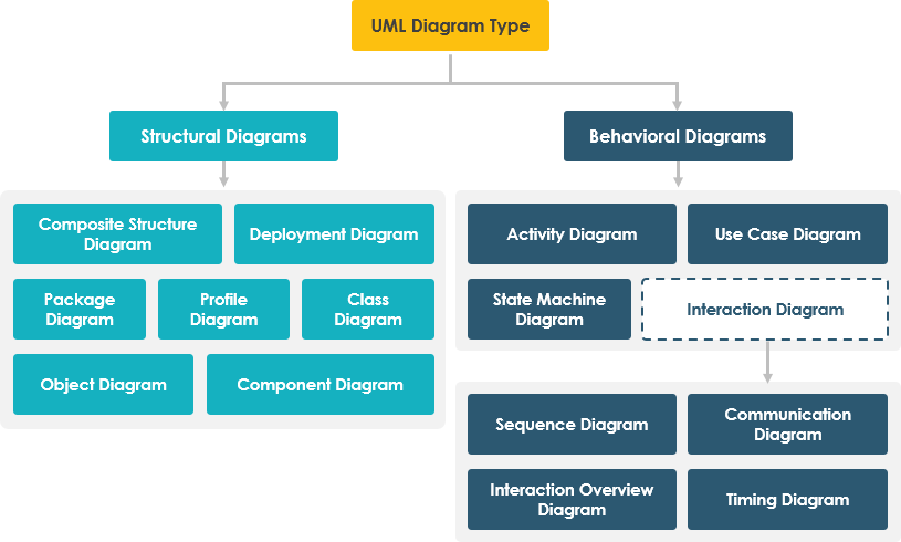
- Structural Diagrams:
- Class Diagram: Shows the static structure of a system, including classes, attributes, methods, and relationships.
- Object Diagram: Represents a snapshot of the objects in a system at a specific point in time.
- Component Diagram: Illustrates the organization and dependencies among a set of components.
- Deployment Diagram: Shows the physical deployment of artifacts on nodes.
- Package Diagram: Depicts how a system is split up into logical groupings.
- Composite Structure Diagram: Shows the internal structure of a class and the collaborations that this structure makes possible.
- Behavioral Diagrams:
- Use Case Diagram: Captures the functional requirements of a system.
- Sequence Diagram: Shows how objects interact in a particular scenario of a use case.
- Activity Diagram: Represents workflows of stepwise activities and actions.
- State Machine Diagram: Shows the sequences of states that an object goes through during its lifetime.
- Communication Diagram: Focuses on the structural relationships between objects and the messages that pass between them.
- Interaction Overview Diagram: Provides a high-level view of interactions in a system.
- Timing Diagram: Shows interactions when a single lifeline is emphasized.
Case Study: Library Management System
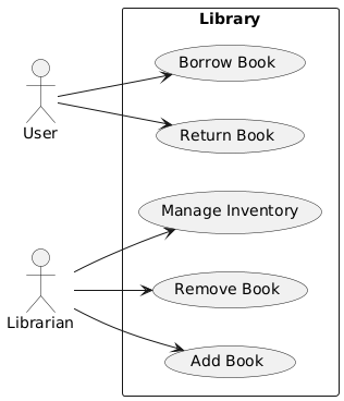
Let’s apply UML to design a Library Management System. This system will allow users to borrow and return books, and librarians to manage the inventory.
1. Use Case Diagram
The Use Case Diagram captures the functional requirements of the Library Management System.
2. Class Diagram
The Class Diagram shows the static structure of the system, including classes, attributes, methods, and relationships.
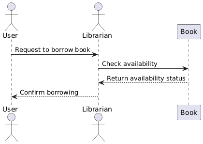
3. Sequence Diagram
The Sequence Diagram shows how objects interact in a particular scenario of a use case, such as borrowing a book.
4. Activity Diagram
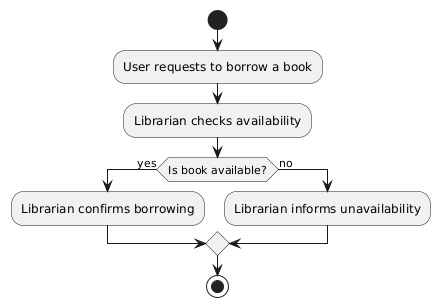
The Activity Diagram represents the workflows of stepwise activities and actions, such as the process of borrowing a book.
5. State Machine Diagram
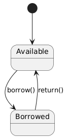
The State Machine Diagram shows the sequences of states that a book goes through during its lifetime.
Recommendation for Visual Paradigm
For developers seeking the ultimate UML tool, Visual Paradigm stands out as an exceptional choice. Visual Paradigm offers a comprehensive suite of features that cater to various modeling needs, including activity diagrams, class diagrams, sequence diagrams, and more. Its intuitive interface and robust functionality make it accessible for both beginners and experienced professionals.
Key benefits of using Visual Paradigm include:
- Comprehensive Modeling Tools: Visual Paradigm supports a wide range of UML diagrams, ensuring that developers can model every aspect of their systems effectively.
- Collaboration Features: The tool facilitates team collaboration with features like version control, real-time collaboration, and shared repositories.
- Integration Capabilities: Visual Paradigm integrates seamlessly with popular development environments and tools, such as Eclipse, Visual Studio, and Git, enhancing the development workflow.
- Customization and Extensibility: Developers can customize diagrams and extend the tool’s functionality with plugins and scripts to meet specific project requirements.
- Documentation and Reporting: Visual Paradigm provides powerful documentation and reporting features, allowing developers to generate detailed reports and documentation directly from their models.
Conclusion
Unified Modeling Language (UML) is an indispensable tool in the software development lifecycle, offering a standardized and visual approach to specifying, constructing, and documenting software systems. Its versatility and wide-ranging applications make it a valuable asset for various stakeholders, from developers and architects to project managers and clients.
UML is a powerful and flexible tool that enhances communication, design, and documentation in software development. Its standardized approach and wide-ranging applications make it an essential asset for various stakeholders, ensuring that the system meets its requirements and is well-understood by all involved parties. By leveraging UML, teams can achieve better collaboration, more efficient development processes, and ultimately, higher-quality software.
Visual Paradigm is a versatile and powerful UML tool that empowers developers to create precise and comprehensive models, fostering better communication, collaboration, and overall project success.

