Introduction
An Entity-Relationship Diagram (ERD) is a visual representation of the data model for a system, illustrating the entities, their attributes, and the relationships between them. ERDs are essential tools in database design and system analysis, helping to understand and communicate the structure of a database. This article will explain the key concepts of ERDs, the three different types of ERDs, their differences, and when to use each type.
Key Concepts of ERDs
- Entities:
- Entities are objects or things in the real world that are distinguishable from other objects. In an ERD, entities are represented by rectangles.
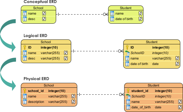
- Example: In the image, “School” and “Student” are entities.
- Attributes:
- Attributes are properties or characteristics of entities. They are represented by ovals or listed inside the entity rectangles.
- Example: The “School” entity has attributes “name” and “desc,” while the “Student” entity has attributes “name” and “date of birth.”
- Relationships:
- Relationships are associations between entities. They are represented by lines connecting the entities.
- Example: The relationship between “School” and “Student” indicates that students are associated with schools.
- Primary Keys:
- Primary keys are attributes that uniquely identify an entity. They are often underlined or marked with a key symbol.
- Example: In the Logical ERD, “ID” is the primary key for both “School” and “Student” entities.
- Foreign Keys:
- Foreign keys are attributes in one entity that refer to the primary key of another entity, establishing a relationship between them.
- Example: In the Logical ERD, “SchoolID” in the “Student” entity is a foreign key that references the “ID” in the “School” entity.
Three Types of ERDs

- Conceptual ERD:
- Definition: A Conceptual ERD provides a high-level overview of the database structure, focusing on the main entities and their relationships without considering the details of the database implementation.
- Purpose: It is used in the early stages of database design to capture the essential data requirements and relationships.
- Example: In the image, the Conceptual ERD shows the “School” and “Student” entities with their basic attributes and relationships.
- When to Use: Use a Conceptual ERD during the initial planning and requirements gathering phase to get a broad understanding of the data model.
- Logical ERD:
- Definition: A Logical ERD provides a more detailed view of the database structure, including primary and foreign keys, data types, and constraints.
- Purpose: It is used to define the logical structure of the database, ensuring data integrity and normalization.
- Example: In the image, the Logical ERD includes the “ID” as the primary key for both “School” and “Student” entities, and “SchoolID” as a foreign key in the “Student” entity.
- When to Use: Use a Logical ERD during the detailed design phase to specify the data model in more detail, ensuring that it meets the functional requirements.
- Physical ERD:
- Definition: A Physical ERD represents the actual implementation of the database in a specific database management system (DBMS), including tables, columns, data types, indexes, and constraints.
- Purpose: It is used to define the physical structure of the database, optimizing performance and storage.
- Example: In the image, the Physical ERD shows the “School” and “Student” tables with specific column names, data types, and relationships.
- When to Use: Use a Physical ERD during the implementation phase to create the database schema in the chosen DBMS, ensuring that it meets the performance and storage requirements.
Differences Between the Three Types of ERDs
- Level of Detail:
- Conceptual ERD: High-level overview, focusing on main entities and relationships.
- Logical ERD: More detailed, including primary and foreign keys, data types, and constraints.
- Physical ERD: Most detailed, including tables, columns, data types, indexes, and constraints.
- Purpose:
- Conceptual ERD: Capture essential data requirements and relationships.
- Logical ERD: Define the logical structure of the database, ensuring data integrity and normalization.
- Physical ERD: Define the physical structure of the database, optimizing performance and storage.
- Usage:
- Conceptual ERD: Used in the initial planning and requirements gathering phase.
- Logical ERD: Used in the detailed design phase.
- Physical ERD: Used in the implementation phase.
When to Use Each Type of ERD
- Conceptual ERD:
- Use during the initial planning and requirements gathering phase to get a broad understanding of the data model.
- Suitable for discussions with stakeholders to capture essential data requirements and relationships.
- Logical ERD:
- Use during the detailed design phase to specify the data model in more detail, ensuring that it meets the functional requirements.
- Suitable for database designers and analysts to define the logical structure of the database.
- Physical ERD:
- Use during the implementation phase to create the database schema in the chosen DBMS, ensuring that it meets the performance and storage requirements.
- Suitable for database administrators and developers to define the physical structure of the database.
Conclusion
Entity-Relationship Diagrams (ERDs) are essential tools in database design and system analysis, providing a visual representation of the data model. The three types of ERDs—Conceptual, Logical, and Physical—serve different purposes and are used at different stages of the database development lifecycle. Understanding the key concepts and differences between these types of ERDs helps in effectively designing, implementing, and managing databases. By using the appropriate type of ERD at each stage, you can ensure that the database meets the functional, performance, and storage requirements, leading to a successful and efficient database system.

