Introduction
Use Case Diagrams are a fundamental tool in software engineering and systems analysis, used to capture and model the functional requirements of a system from the user’s perspective. These diagrams visually represent the interactions between users (actors) and the system, helping to identify and document the system’s behavior and functionality.
This article will explain the key concepts of use case diagrams, with a particular focus on the “include” and “extend” relationships, using the Bulletin Board System (BBS) example to illustrate these concepts and their utility in requirement modeling.
Key Concepts in Use Case Diagrams

1. Actors
- Definition: Actors represent the users or external systems that interact with the system.
- Example: In the Bulletin Board System, the actor is “Members.”
2. Use Cases
- Definition: Use cases describe the specific interactions between actors and the system to achieve particular goals.
- Components: Use case name, brief description, actors involved, preconditions, postconditions, main success scenario, and alternative scenarios.
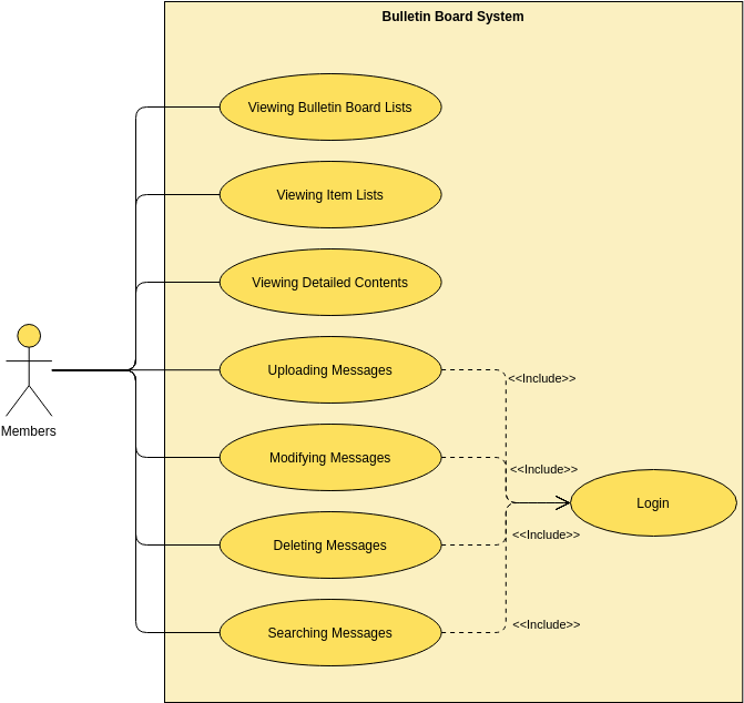
- Example: In the BBS, use cases include “Viewing Bulletin Board Lists,” “Viewing Item Lists,” “Viewing Detailed Contents,” “Uploading Messages,” “Modifying Messages,” “Deleting Messages,” and “Searching Messages.”
3. Use Case Diagram
- Definition: A use case diagram is a visual representation of the actors, use cases, and their relationships.
- Elements: Actors (represented by stick figures), use cases (represented by ovals), and relationships (represented by lines).
- Example: The BBS use case diagram shows the actor “Members” interacting with various use cases related to managing and viewing messages on the bulletin board.
4. Relationships
- Types:
- Association: A line connecting an actor to a use case, indicating that the actor participates in that use case.
- Include: A relationship between use cases where one use case includes the behavior of another use case.
- Extend: A relationship between use cases where one use case extends the behavior of another use case under certain conditions.
- Generalization: A relationship between actors or use cases where one actor or use case is a specialized version of another.
Include Relationship
Definition
The “include” relationship is used when a use case contains the behavior of another use case. It indicates that the included use case is a mandatory part of the base use case.
Example in BBS
In the Bulletin Board System, the use cases “Uploading Messages,” “Modifying Messages,” “Deleting Messages,” and “Searching Messages” all include the “Login” use case. This means that to perform any of these actions, the member must first log in to the system.
Utility
The “include” relationship helps in modularizing the use cases and avoiding redundancy. By including the “Login” use case, we ensure that the login process is a mandatory step for these actions, and we don’t need to repeat the login steps in each use case description.
Extend Relationship
Definition
The “extend” relationship is used when a use case adds behavior to another use case under certain conditions. It indicates that the extending use case is an optional part of the base use case.
Example in BBS
In the BBS, an example of an “extend” relationship could be a use case like “Sending Notifications” that extends the “Uploading Messages” use case. This means that under certain conditions, such as when a message is uploaded, a notification might be sent to other members.
Utility
The “extend” relationship helps in capturing optional behaviors and exceptions. It allows for the addition of extra functionality without altering the base use case, making the system more flexible and adaptable to different scenarios.
Why Use Case Diagrams are Useful for Requirement Modeling
1. User-Centric Approach
Use case diagrams focus on the user’s perspective, ensuring that the system meets the users’ needs and expectations. By identifying actors and their interactions with the system, we can design a system that is intuitive and user-friendly.
2. Clear Requirements
Use case diagrams help in capturing and documenting the functional requirements of the system in a clear and concise manner. Each use case represents a specific goal or functionality, making it easier to understand and manage the system’s requirements.
3. Communication Tool
Use case diagrams serve as a communication tool between stakeholders, developers, and users. They provide a visual representation of the system’s functionality, ensuring that everyone has a shared understanding of the system’s behavior and requirements.
4. Identifying Gaps
By analyzing use cases, potential gaps and inconsistencies in the system’s requirements can be identified and addressed early in the development process. This helps in creating a more robust and reliable system.
5. Test Cases
Use cases can be used to derive test cases, ensuring that the system is tested thoroughly and meets the specified requirements. Each use case can be translated into one or more test cases, covering both the main success scenario and alternative scenarios.
Conclusion
Use Case Diagrams are a powerful tool for understanding, capturing, and documenting the functional requirements of a system from the user’s perspective. By identifying actors, describing use cases, creating use case diagrams, and analyzing use cases, developers and stakeholders can ensure that the system meets the users’ needs and provides the desired functionality. The “include” and “extend” relationships in use case diagrams help in modularizing the use cases, avoiding redundancy, and capturing optional behaviors and exceptions.
For organizations looking to create use case diagrams and other visual representations of their systems, tools like Visual Paradigm offer a range of features and templates to streamline the process. Visit Visual Paradigm to explore the available tools and start creating your use case diagrams today.

