

Introduction to UML
Unified Modeling Language (UML) is a standardized modeling language used to visualize, specify, construct, and document the artifacts of a software-intensive system. UML provides a common language for project stakeholders, allowing them to capture and communicate complex software system designs effectively.
UML consists of several types of diagrams, each serving a specific purpose in the software development lifecycle. These diagrams can be categorized into structural diagrams, behavioral diagrams, and interaction diagrams.
Structural Diagrams
Structural diagrams focus on the static aspects of a system, representing the elements that make up the system and how they are related. Some common structural diagrams include:
- Class Diagram: Depicts the classes in a system, their attributes, operations, and the relationships between them.
- Component Diagram: Represents the high-level components of a system and their dependencies.
- Deployment Diagram: Illustrates the hardware nodes and the software components deployed on them.
Behavioral Diagrams
Behavioral diagrams focus on the dynamic aspects of a system, representing the behavior of the system or its parts. Some common behavioral diagrams include:
- Use Case Diagram: Captures the interactions between the system and its users (actors) in the form of use cases.
- Activity Diagram: Describes the flow of activities and actions within a system.
- Sequence Diagram: Models the interactions between objects in a particular scenario, emphasizing the time sequence of messages.
Interaction Diagrams
Interaction diagrams are a subset of behavioral diagrams and focus on the flow of control and data between the elements of a system. Some common interaction diagrams include:
- Sequence Diagram: Models the interactions between objects in a particular scenario, emphasizing the time sequence of messages.
- Communication Diagram: Depicts the interactions between objects, focusing on the structural organization of the objects that send and receive messages.
Case Study: Modeling an Online Retail System
To illustrate the application of UML, let’s consider a case study of an online retail system.
System Requirements
The online retail system allows customers to browse and purchase products, manage their accounts, and track their orders. The system also provides an admin interface for managing products, orders, and customer information.
UML Diagrams
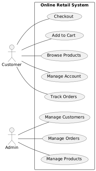
- Use Case Diagram:
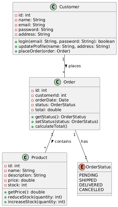
- Class Diagram:
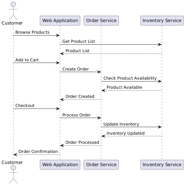
- Sequence Diagram:
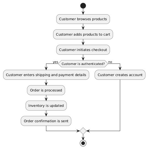
Activity Diagram:
Benefits of UML Modeling
UML modeling provides several benefits in the software development process, including:
- Improved Communication: UML diagrams serve as a common language for project stakeholders, facilitating better understanding and collaboration.
- Increased Productivity: UML models help identify and resolve design issues early in the development lifecycle, leading to more efficient development.
- Maintainability and Scalability: Well-structured UML models make it easier to understand, modify, and extend the system over time.
- Visualization of Complex Systems: UML diagrams provide a visual representation of the system, making it easier to comprehend and analyze.
- Standardization: UML is a widely-adopted standard, enabling better integration and collaboration across different teams and organizations.
Conclusion
UML is a powerful tool in the software development arsenal, providing a comprehensive set of diagrams for modeling and communicating software system designs. By leveraging UML, development teams can improve communication, increase productivity, and create more maintainable and scalable software systems. The case study presented in this article demonstrates the practical application of UML in the context of an online retail system, highlighting the benefits and versatility of this modeling language.