


In software development, visual modeling techniques are essential for understanding and documenting processes. Activity diagrams and sequence diagrams are two powerful tools that can help represent use cases and their various scenarios effectively. This article outlines how to use activity diagrams to represent use cases and how to detail each scenario with sequence diagrams.
Understanding Use Cases
A use case describes a specific interaction between a user (or actor) and a system to achieve a particular goal. It outlines the functional requirements of a system from a user’s perspective. Each use case may have multiple scenarios, including the main success scenario and various alternative paths.
Step 1: Identify the Use Case
Begin by identifying the use case you want to model. This typically involves:
- Gathering Requirements: Understand the needs of the stakeholders.
- Defining Actors: Identify the users or systems that will interact with the use case.
- Establishing Goals: Clearly define what the use case aims to achieve.
Step 2: Create the Activity Diagram
An activity diagram captures the flow of actions within a use case and helps visualize the overall process. Here’s how to create one:
- Define Activities: List the activities involved in the use case, including both user actions and system responses.
- Identify Decision Points: Determine where choices need to be made that affect the flow of the process.
- Map the Flow: Use arrows to indicate the sequence of activities. Start with the initial state and end with the final result.
- Incorporate Parallel Activities: If multiple actions can occur simultaneously, represent them using fork nodes.
- Review and Refine: Ensure the diagram accurately reflects the use case scenario and is easy to understand.
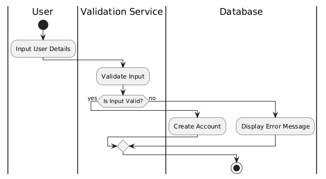
Example of an Activity Diagram
- Use Case: User Registration
- Start
- Input User Details
- Validate Input
- If valid, proceed to Create Account
- If invalid, display Error Message
- End
Step 3: Identify Scenarios
Once the activity diagram is complete, identify the various scenarios of the use case:
- Main Success Scenario: The ideal flow where everything works as intended.
- Alternative Scenarios: Paths that represent errors or alternative choices.
Step 4: Create Sequence Diagrams for Each Scenario
A sequence diagram illustrates how objects interact in a particular scenario over time. For each identified scenario, follow these steps:
- Identify Objects: Determine the objects (actors, systems) involved in the scenario.
- Define Messages: List the messages exchanged between objects, representing function calls, responses, or data flows.
- Map the Sequence: Arrange the objects horizontally and draw vertical lines to represent their lifelines. Use arrows to show message flows in the order they occur.
- Include Activation Boxes: Indicate periods during which an object is active or processing a message.
- Review: Ensure the sequence diagram accurately represents the interactions for the specific scenario.
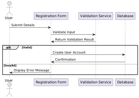
Example of a Sequence Diagram for User Registration
- Objects: User, Registration Form, Validation Service, Database
- Messages:
- User → Registration Form: Submit Details
- Registration Form → Validation Service: Validate Input
- Validation Service → Registration Form: Return Validation Result
- Registration Form → Database: Create User Account
- Database → Registration Form: Confirmation
Conclusion
Using activity and sequence diagrams together provides a comprehensive view of a use case and its scenarios. The activity diagram offers an overview of the process flow, while sequence diagrams detail the interactions within individual scenarios. This structured approach enhances understanding, aids communication among stakeholders, and serves as a valuable reference throughout the development process.
This post is also available in Deutsch, Español, فارسی, Français, English, Bahasa Indonesia, 日本語, Polski, Portuguese, Ру́сский, Việt Nam, 简体中文 and 繁體中文.