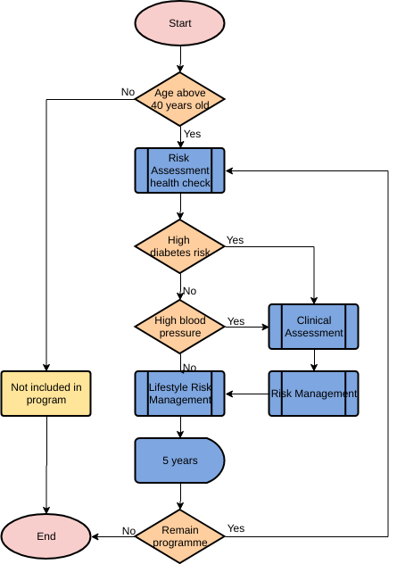
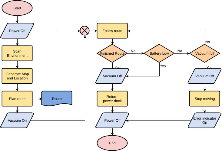
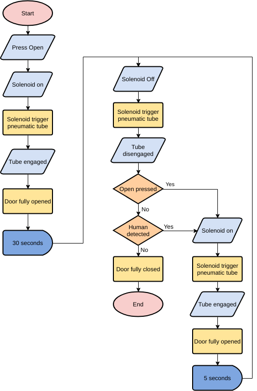
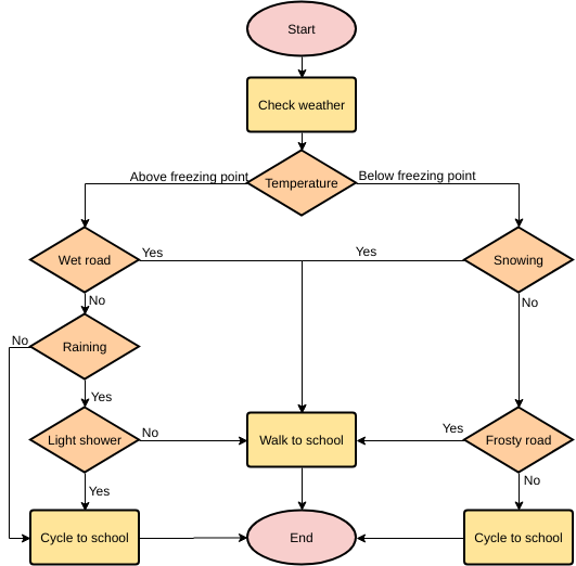
A flowchart is a graphical representation of an algorithm, workflow, or process, with different types of boxes representing different types of steps, and arrows connecting every two steps. This representation facilitates the illustration of solutions to known problems. Flowcharts are widely used to analyze, design, document, and operate processes or procedures in many fields.
What is a Flowchart?
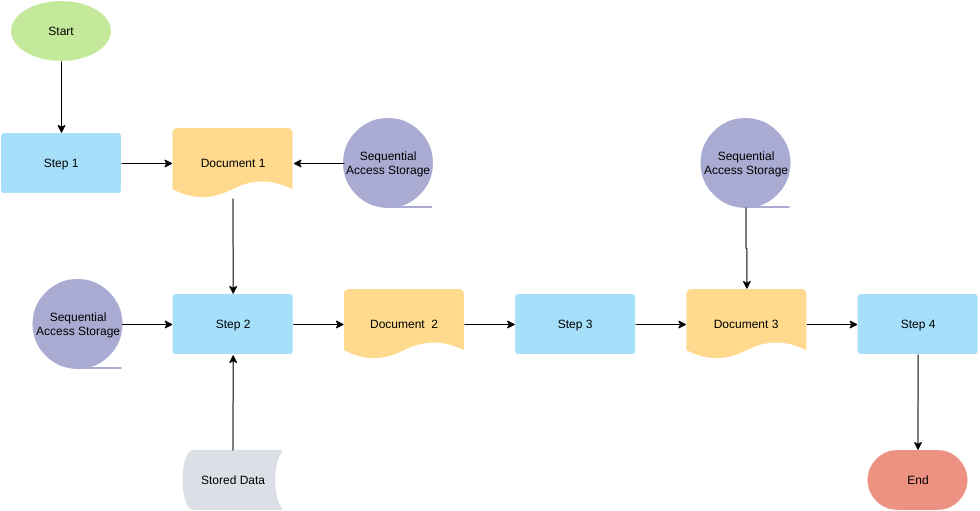
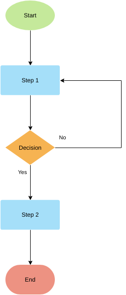
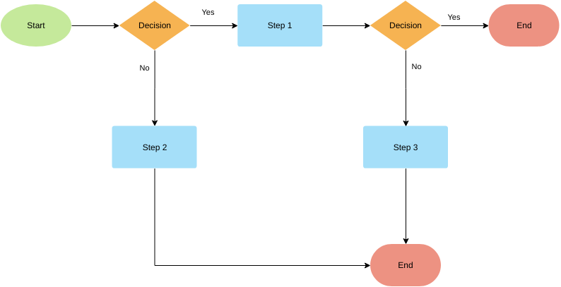
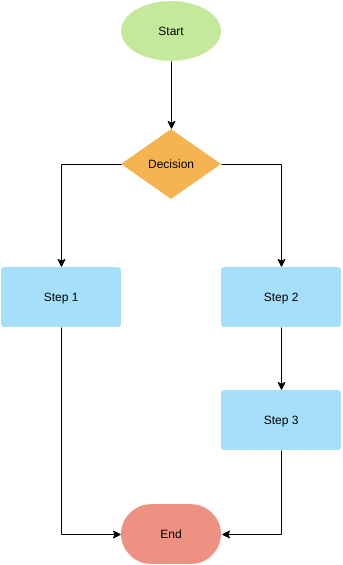
Flowcharts can be used to design or document a number of simple steps or procedures. Like other diagrams, such diagrams can help visualize what is happening and make it easier to understand the process in between. Although there are many variants of flowcharts, each with its own way of labeling, most have the following two symbols.
- Step. Often referred to as “activity” and usually represented by a rectangle
- Decision. Often referred to as an “activity” and usually represented by a rectangle Often represented by a diamond
Advantages and Disadvantages of a Flowchart
- Advantages: intuitive, easy to understand, easy to find errors in the algorithm, can be directly translated into a program.
- Disadvantages: It takes up a lot of space. Due to the use of flow lines, it is too flexible and unconstrained. Users can turn the flow at will, causing difficulties in reading and modifying the program, which is not conducive to the design of structured programs.
Cross-Functional Flowchart
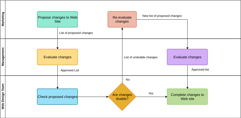
Cross-functional flowchart is often used when a flowchart is divided into different horizontal or vertical sections that are used to describe different control units. A specific control unit will appear as an icon along with a specific section.
Cross-functional flowcharts allow the mapper to correctly assign responsibilities to “execution steps” or “decisions” and show the responsibilities of the component units for each different part of the process.
The Standard Symbols of Flowchart
Flowchart commonly used symbols in order to make the flowchart expressed in the content for others to accurately and comprehensively understand the need to use common, unified flowchart symbols in the diagramming.
At present, the International Organization for Standardization (ISO) and other institutions have flowchart symbol standards can be used as the basis for drawing, such as the need to use this standard in the actual work of graphics and other symbols, should consider its universality, try to use the community has and common, in the case of innovation must indicate the meaning and use of these symbols, and pay attention to the same diagram and later in the actual drawing to maintain the necessary continuity, and Reduce unnecessary types of symbols.
The following table lists the most common flowchart symbols.
Other Additional Symbols
In addition to the above basic symbols, examples are as follows
Tips for Creating Flowchart
The following guidelines must be followed when preparing flowcharts.
- Standard symbols should be used when drawing flowcharts.
- Make sure the flowchart has a starting point (or beginning) and an ending point (or end).
- Avoid crossover of process lines
- The usual orientation of a flowchart is top to bottom or left to right.
- The terminal symbols, i.e. START/BEGIN or STOP/END should have only one flow line.
- The flowchart should be neat, clean, and easy to understand. There should not be any ambiguity.
- Only one process line should come out of the process symbol.
- Only one process line goes into the decision symbol, but there can be two or three process lines, one for each possible answer, leaving the decision symbol.
- If the flowchart is long and complex, connector symbols should be used to reduce the number of process lines.
- Use annotation symbols to describe the steps more clearly.
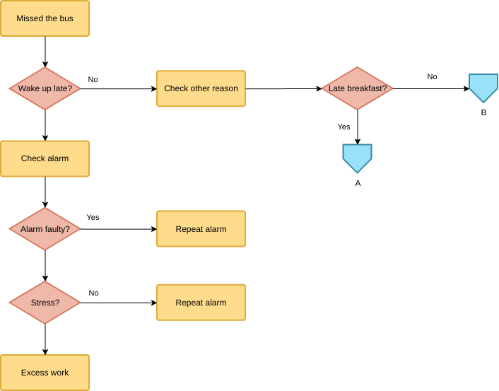
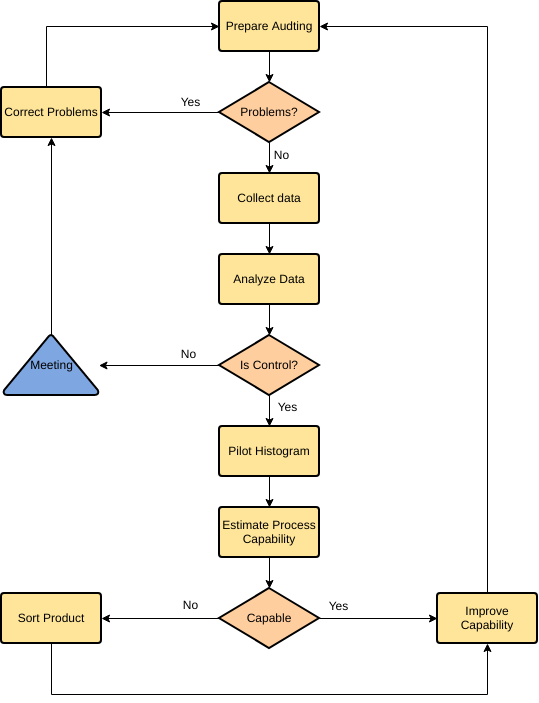
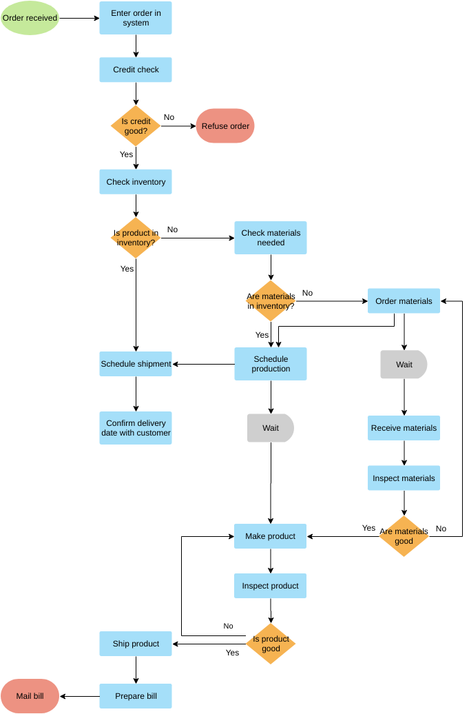
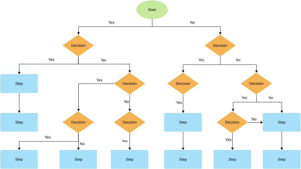
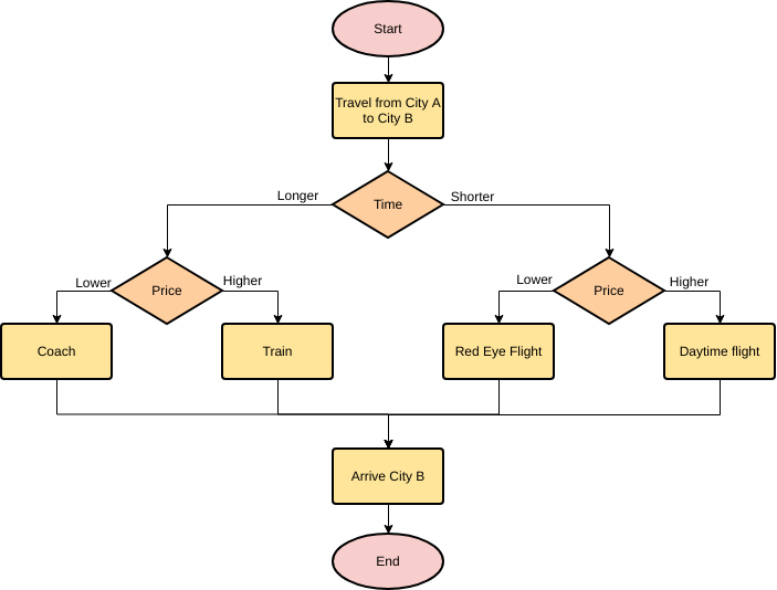
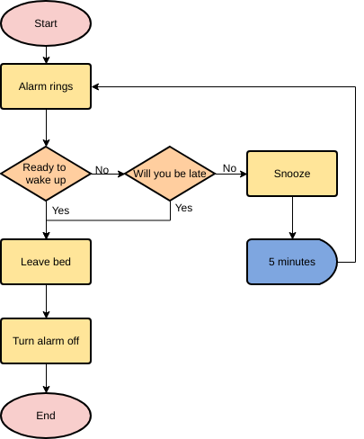
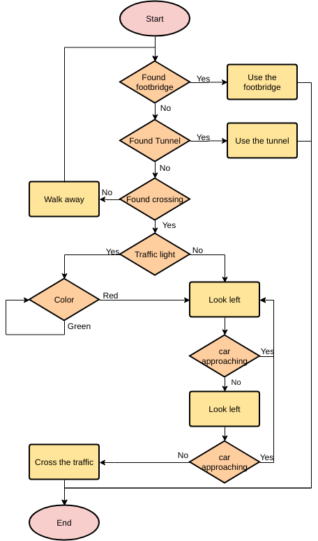
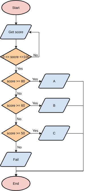
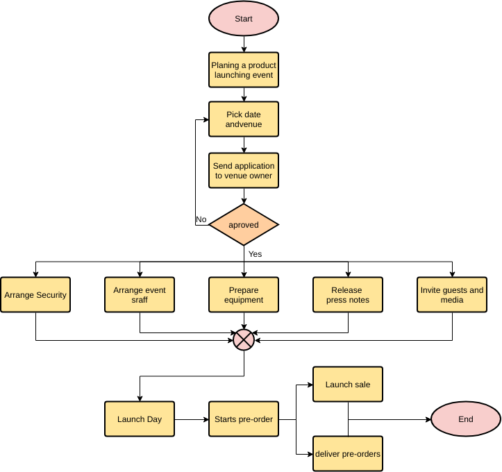
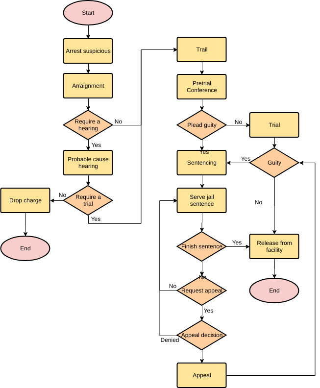
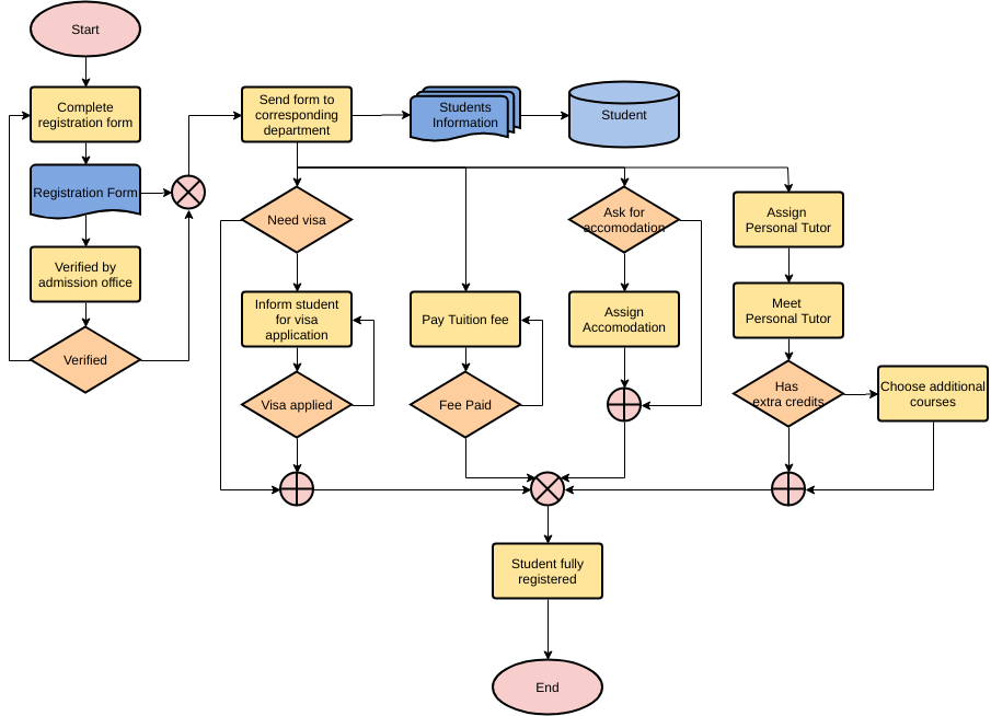
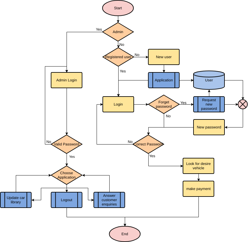
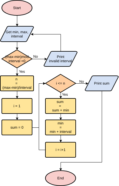
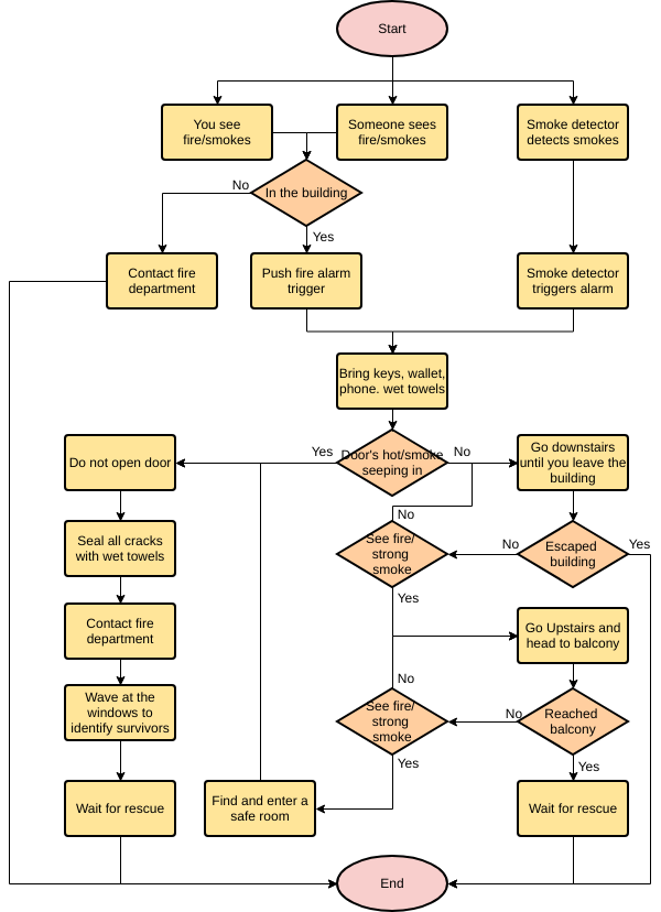
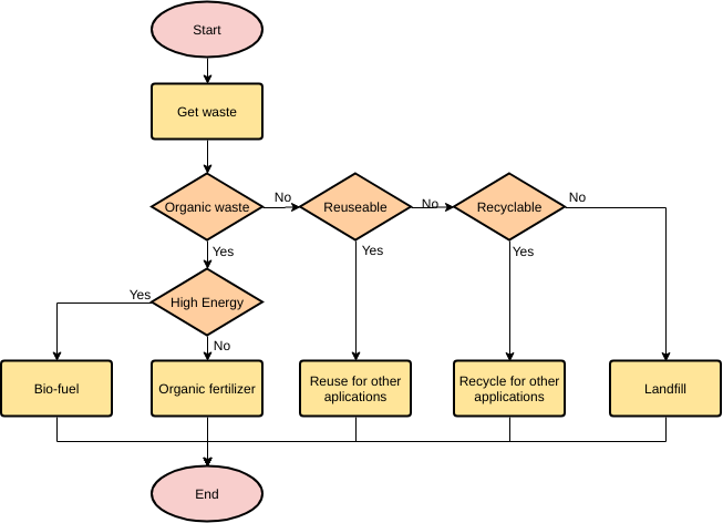
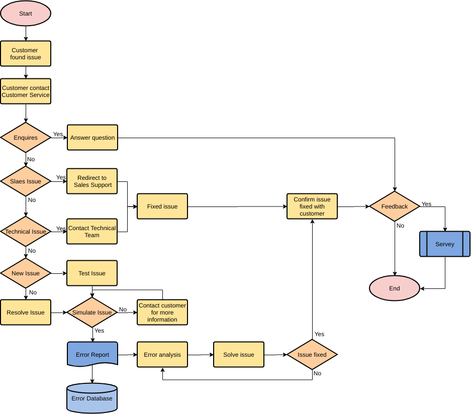
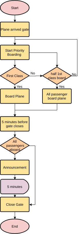
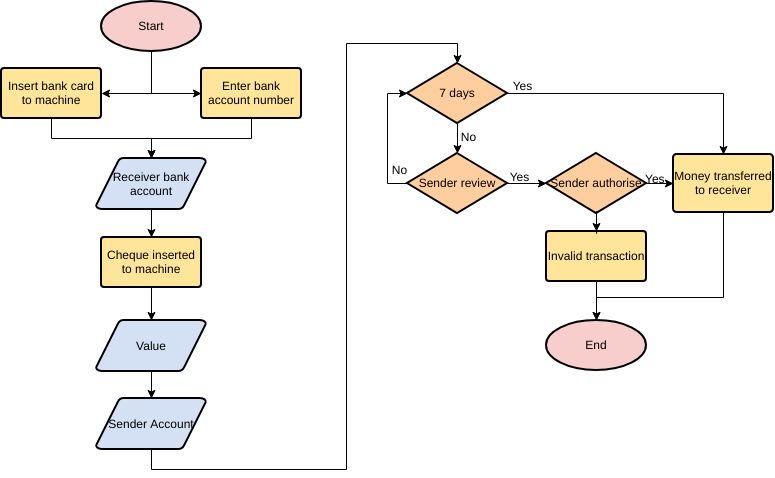
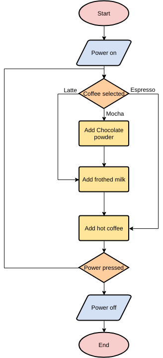
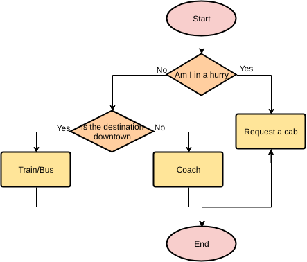
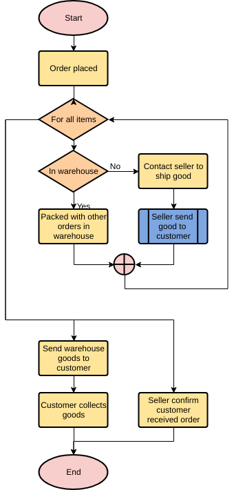
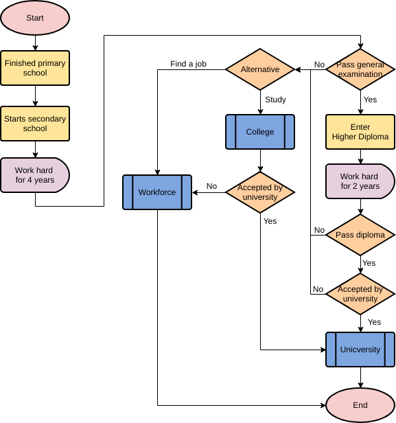
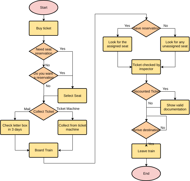
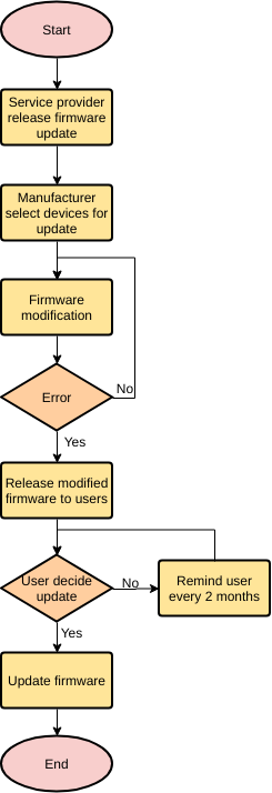
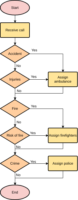
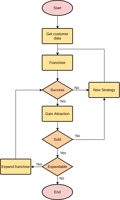
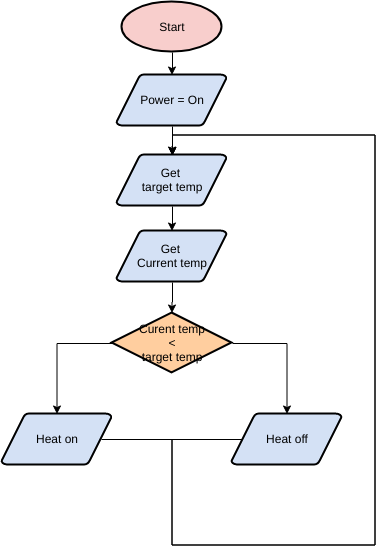
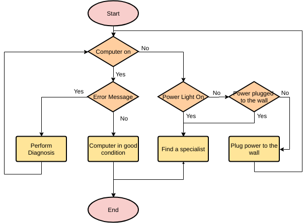
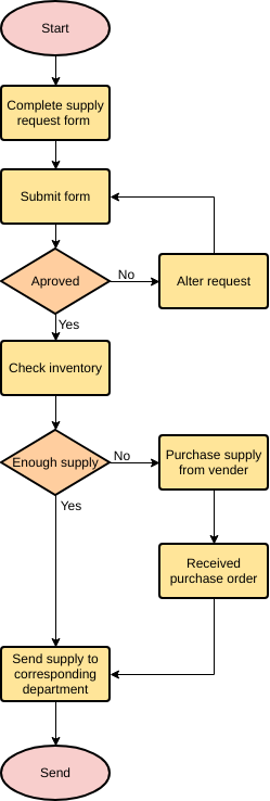
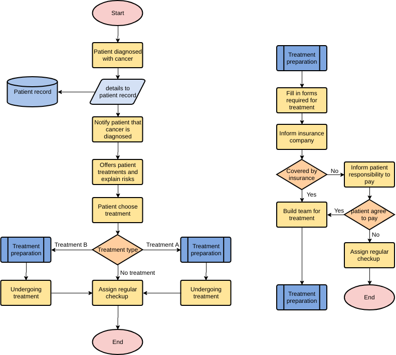
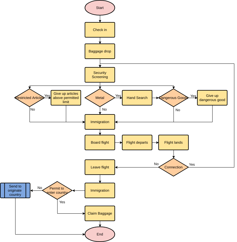
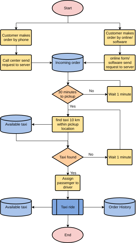
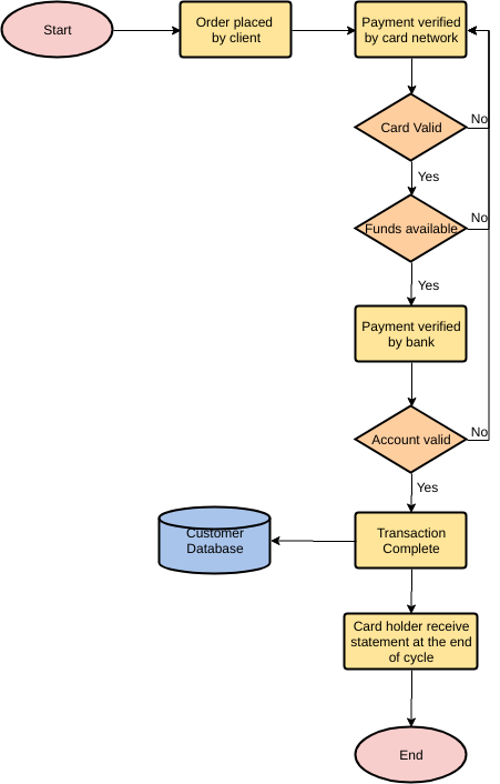
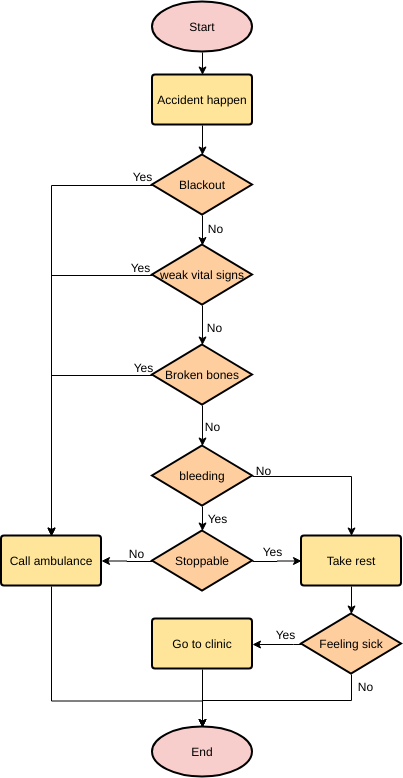
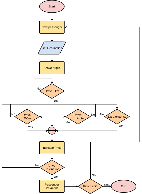
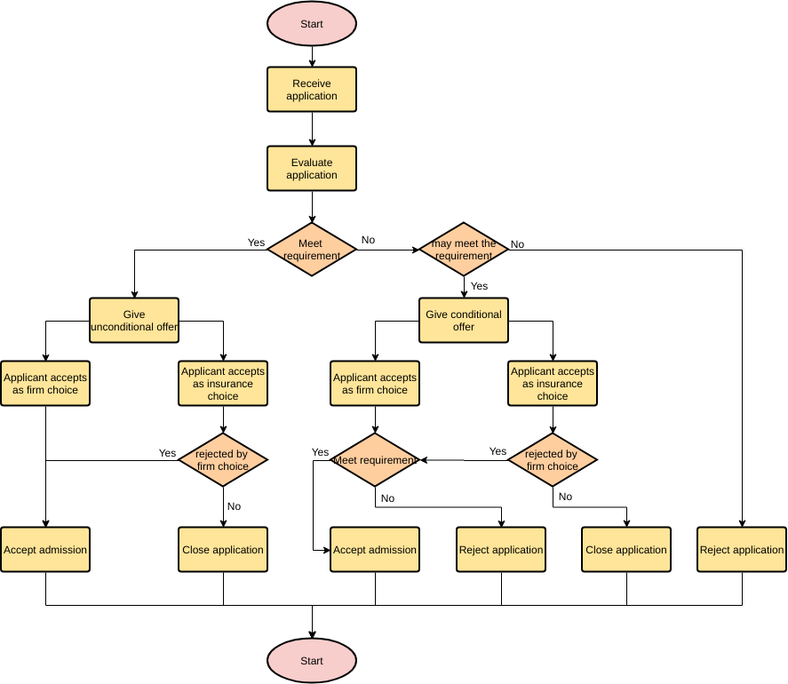
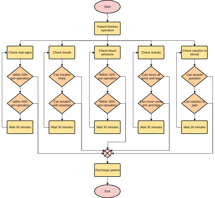
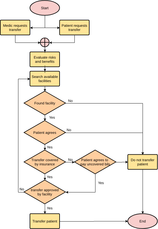
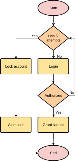
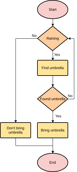
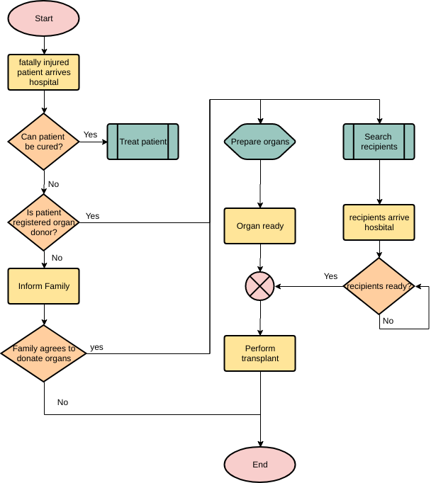
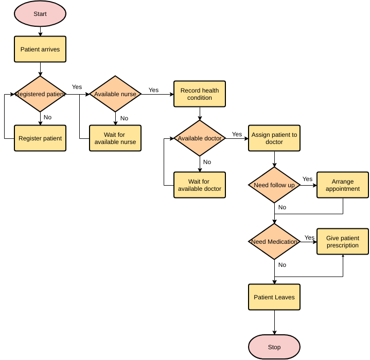
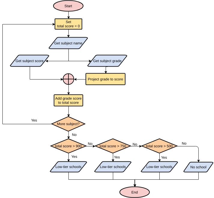
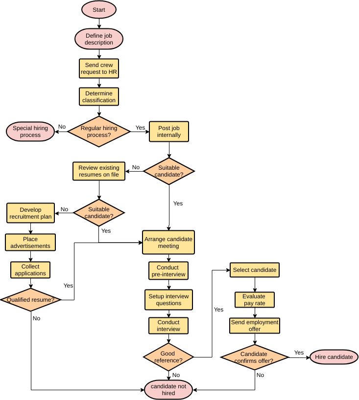
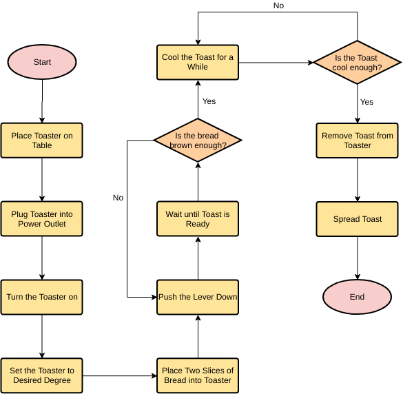
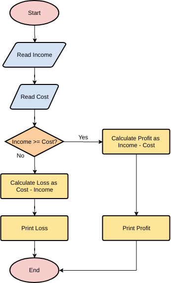
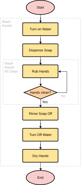
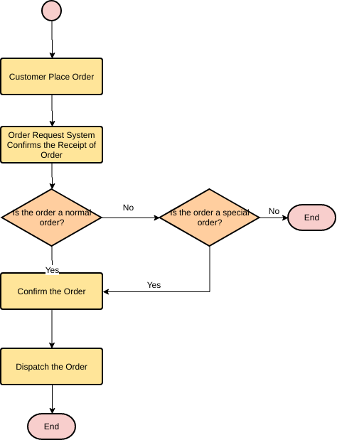
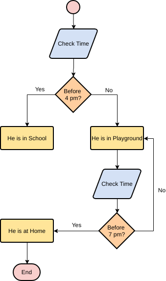
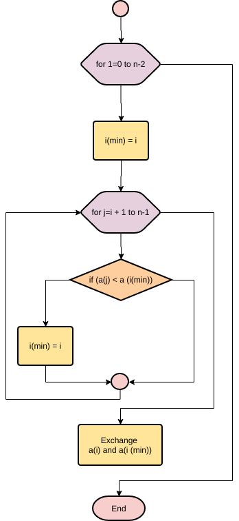
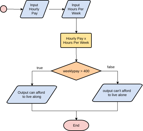
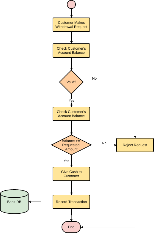
Learning Flowchart by Examples
Explore more Cross Functional Flowchart templates
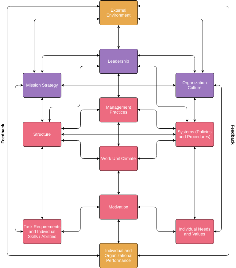
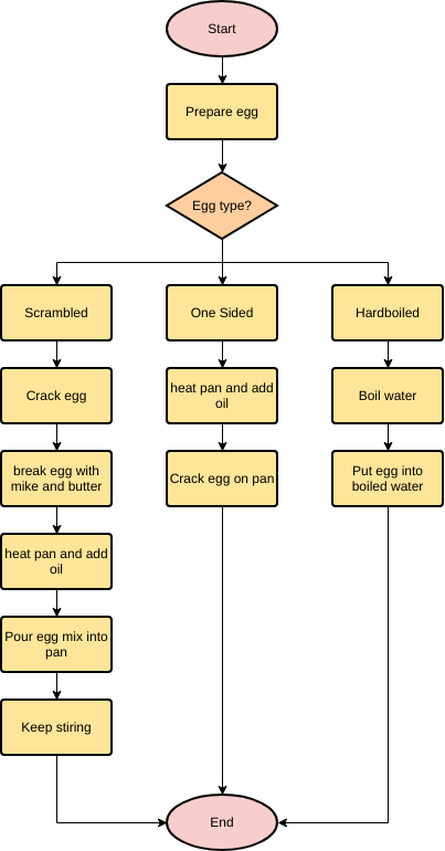
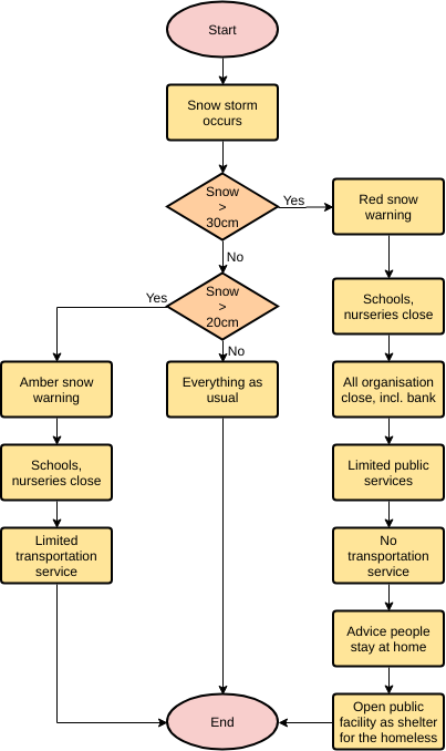
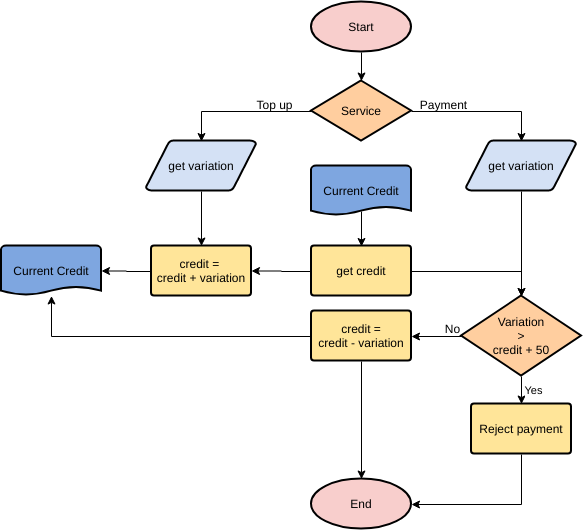
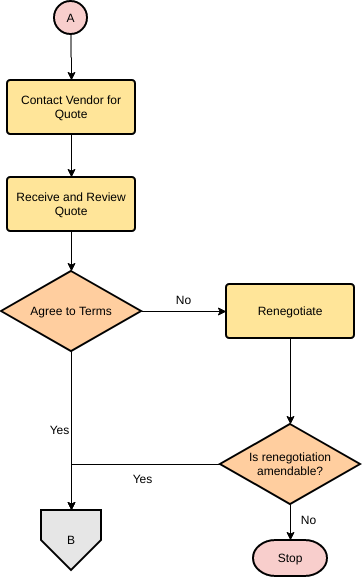
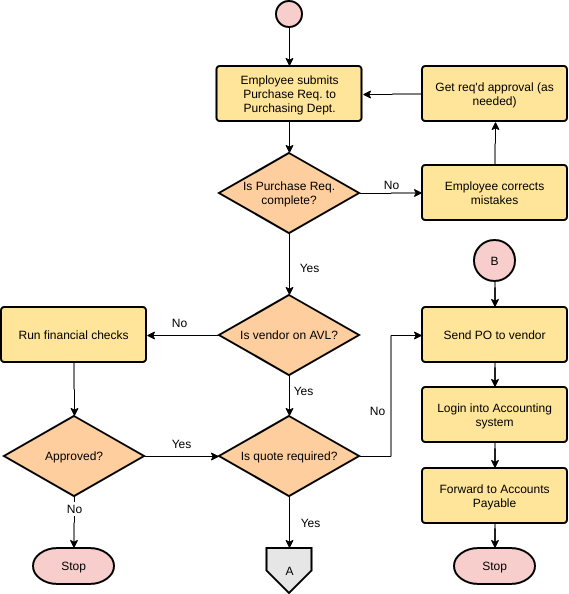
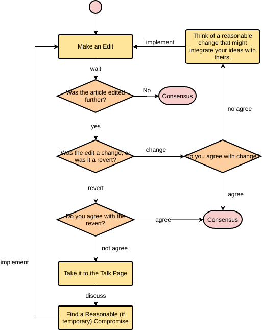
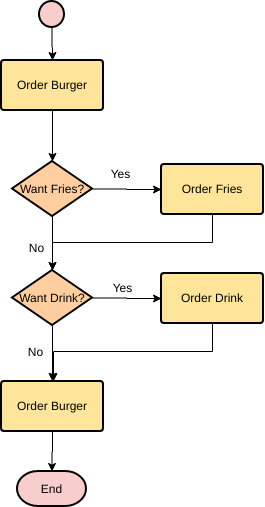
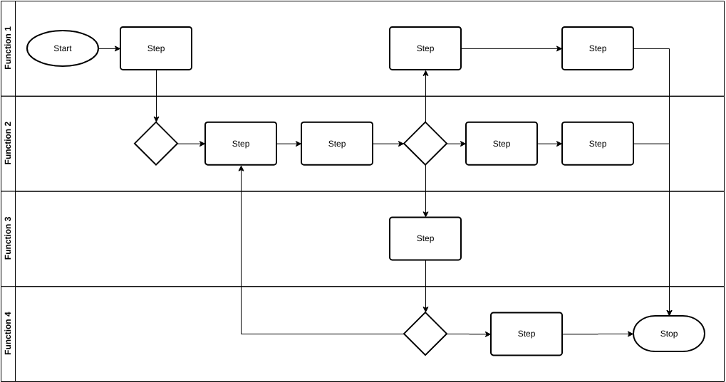
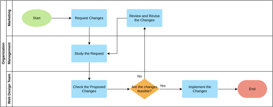
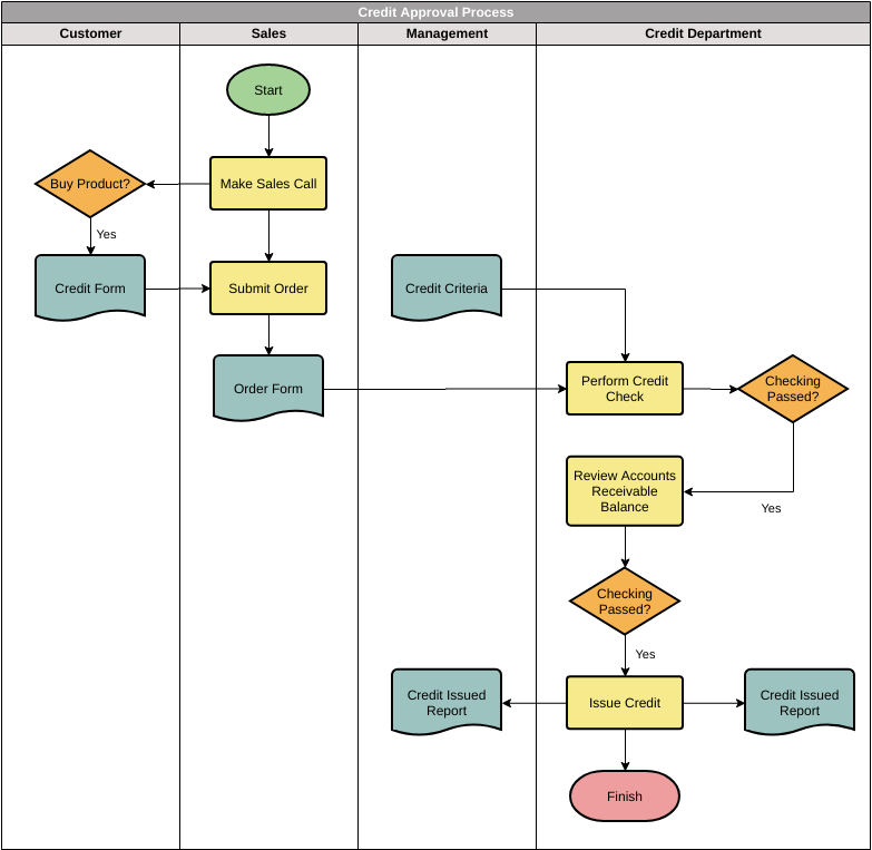
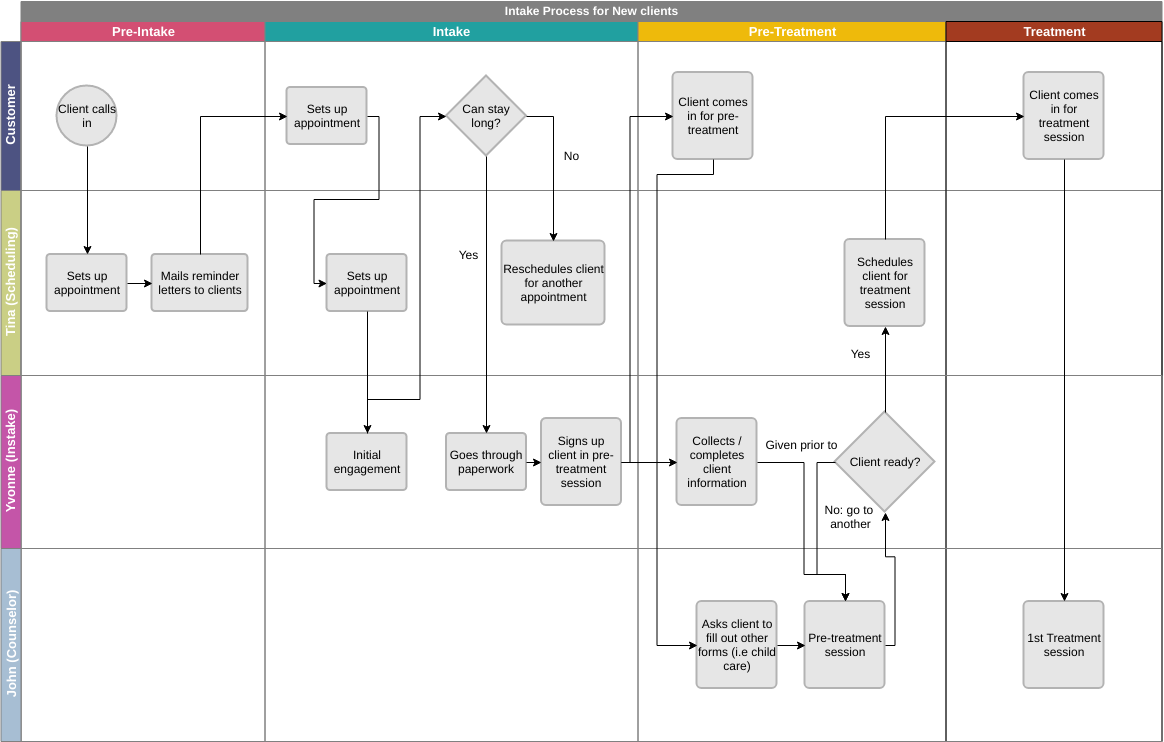
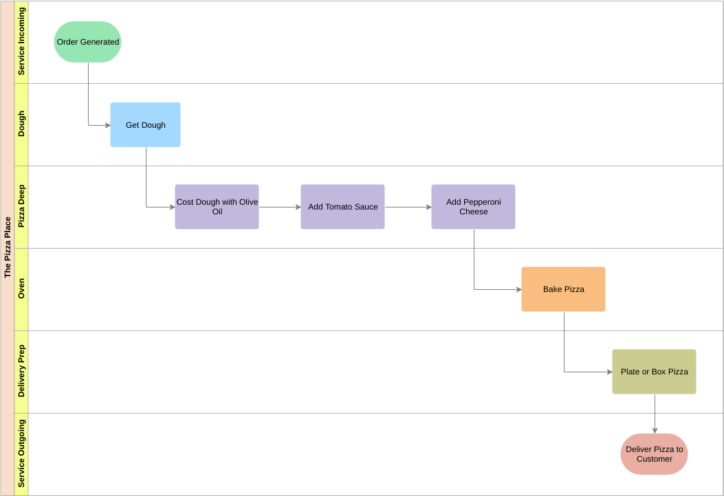
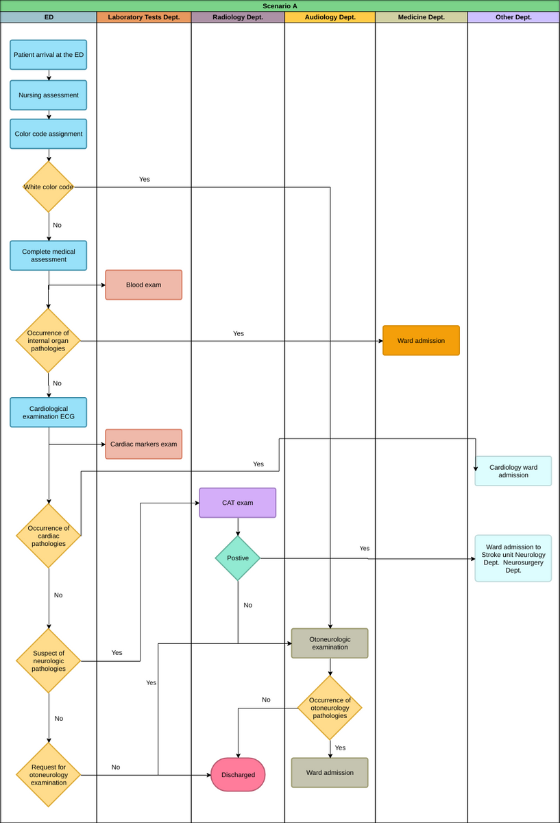
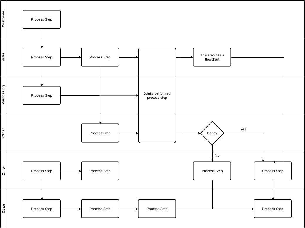
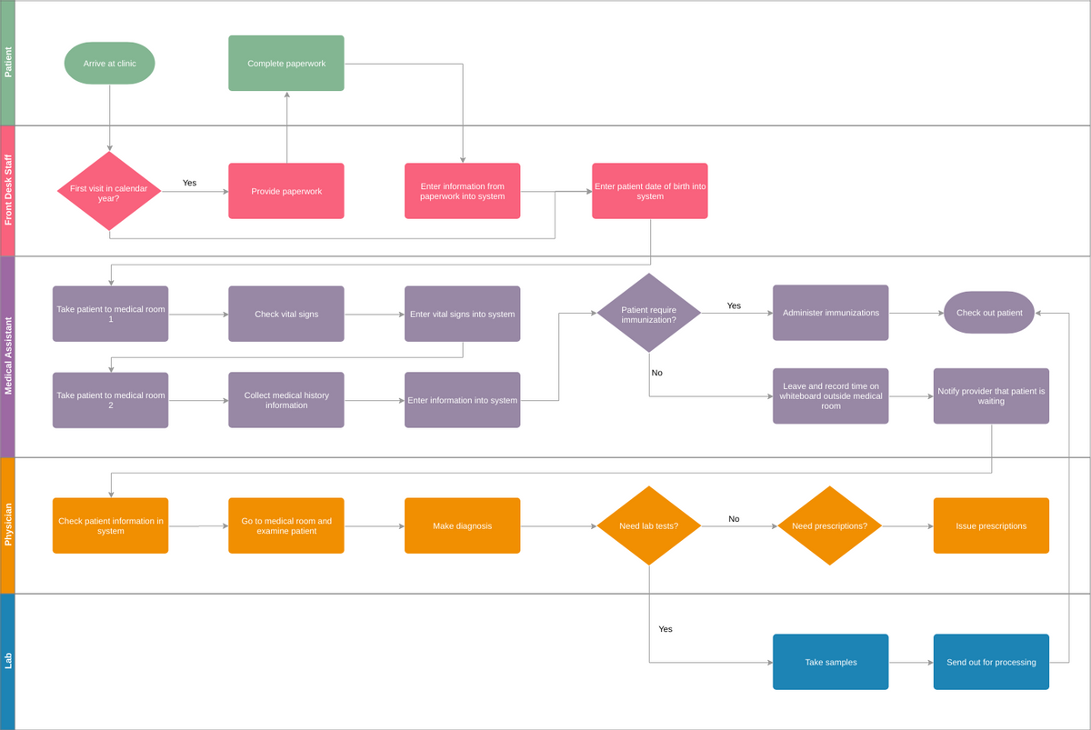
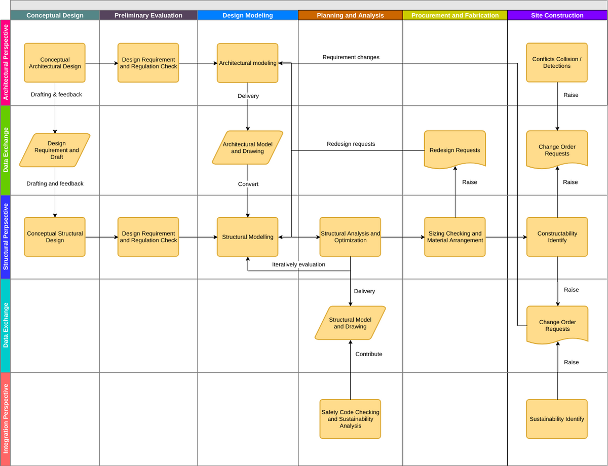
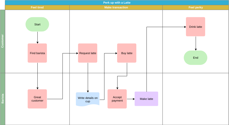
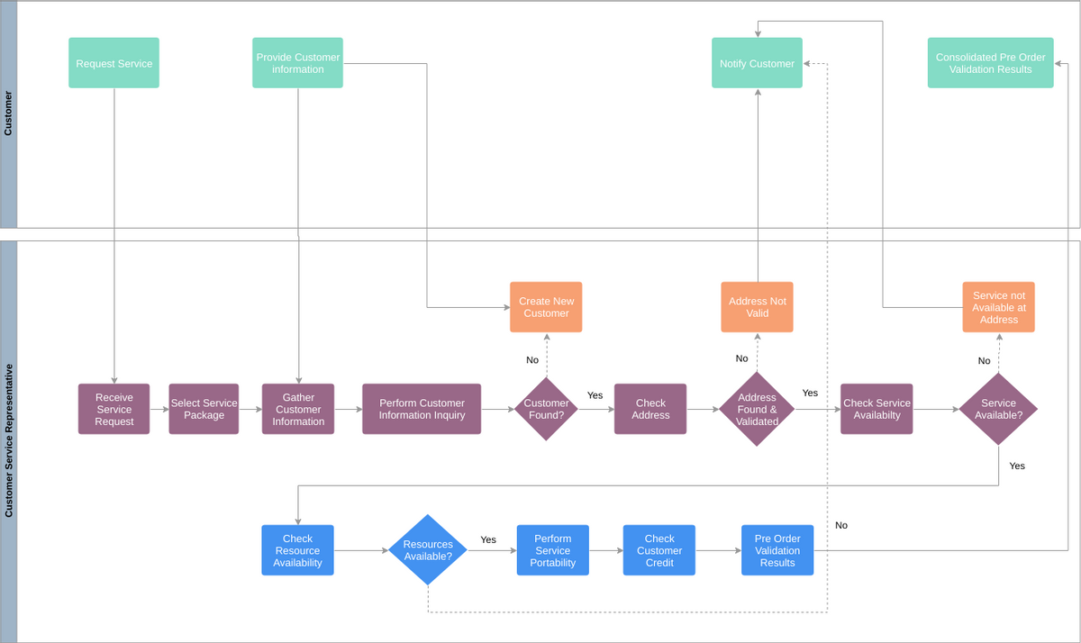
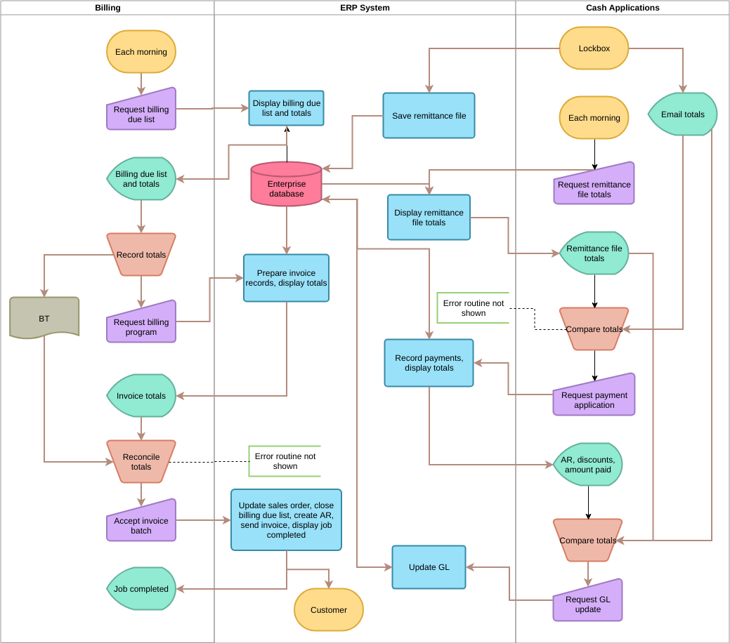
A cross-functional process map reveals who does what and when, organized into sections in a grid-like diagram. It goes beyond the basic process map and shows the relationship between functions (e.g., stakeholders or departments) and stages (e.g., milestones) in the process, here are some cross functional flowchart templates and examples:







how to buy priligy in usa reviews So I used clomid on CD 3- 7 of this cycle