BPMN là gì
Sáng kiến Quản lý Quy trình Kinh doanh (BPMI) đã phát triển một ký hiệu Mô hình Quy trình Kinh doanh tiêu chuẩn (BPMN). Đặc tả BPMN 1.0 đã được công bố công khai vào tháng 5 năm 2004. Đặc tả này đại diện cho hơn hai năm nỗ lực của Nhóm làm việc về Ký hiệu BPMI. Một tài liệu Đặc tả BPMN đã được OMG phát hành vào tháng 2 năm 2006. Phiên bản 2.0 của BPMN được phát triển vào năm 2010, và phiên bản thực tế của đặc tả đã được phát hành vào tháng 12 năm 2013.
Mục tiêu của BPMN
Mục tiêu chính của nỗ lực BPMN là cung cấp một ký hiệu dễ hiểu cho tất cả người dùng kinh doanh, từ các nhà phân tích kinh doanh tạo ra các bản nháp ban đầu của quy trình, đến các nhà phát triển kỹ thuật chịu trách nhiệm triển khai công nghệ sẽ thực hiện các quy trình đó, và cuối cùng, đến những người kinh doanh sẽ quản lý và giám sát các quy trình đó.
Triển khai BPMN
BPMN cũng sẽ được hỗ trợ bằng một mô hình nội bộ cho phép tạo ra BPEL4WS có thể thực thi. Do đó, BPMN tạo ra một cầu nối tiêu chuẩn hóa cho khoảng cách giữa thiết kế quy trình kinh doanh và triển khai quy trình.
Một BPMN đơn giản
BPMN định nghĩa một Sơ đồ Quy trình Kinh doanh (BPD), dựa trên một kỹ thuật lập biểu đồ dòng chảy được điều chỉnh để tạo ra các mô hình đồ họa của các hoạt động quy trình kinh doanh. Một Mô hình Quy trình Kinh doanh, do đó, là một mạng lưới các đối tượng đồ họa, bao gồm các hoạt động (tức là, công việc) và các điều khiển dòng chảy xác định thứ tự thực hiện của chúng.

Các khái niệm chính của BPMN
Một BPD được tạo thành từ một tập hợp các yếu tố đồ họa. Những yếu tố này cho phép phát triển dễ dàng các sơ đồ đơn giản mà sẽ trông quen thuộc với hầu hết các nhà phân tích kinh doanh (ví dụ: một sơ đồ biểu đồ dòng chảy).
Các yếu tố được chọn để có thể phân biệt với nhau và sử dụng các hình dạng quen thuộc với hầu hết các nhà mô hình hóa. Ví dụ, các hoạt động là hình chữ nhật và các quyết định là hình thoi. Cần nhấn mạnh rằng một trong những động lực cho sự phát triển của BPMN là tạo ra một cơ chế đơn giản để tạo ra các mô hình quy trình kinh doanh, trong khi vẫn có thể xử lý sự phức tạp vốn có của các quy trình kinh doanh.
Cách tiếp cận được thực hiện để xử lý hai yêu cầu mâu thuẫn này là tổ chức các khía cạnh đồ họa của ký hiệu thành các danh mục cụ thể. Điều này cung cấp một tập hợp nhỏ các danh mục ký hiệu để người đọc BPD có thể dễ dàng nhận ra các loại yếu tố cơ bản và hiểu sơ đồ. Trong các danh mục cơ bản của các yếu tố, có thể thêm biến thể và thông tin bổ sung để hỗ trợ các yêu cầu về độ phức tạp mà không làm thay đổi đáng kể hình thức và cảm nhận cơ bản của sơ đồ.
Bốn danh mục cơ bản của các yếu tố là:
- Các đối tượng dòng chảy (sự kiện / hoạt động / Cổng)
- Các đối tượng kết nối(dòng chảy tuần tự / dòng chảy tin nhắn / liên kết)
- Các làn bơi(bể / làn)
- Các đối tượng (Đối tượng Dữ liệu / Nhóm / Chú thích)
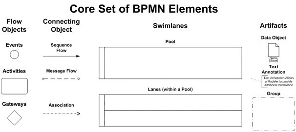
Các đối tượng dòng chảy Một BPD có một tập hợp nhỏ (ba) yếu tố cốt lõi, đó là các đối tượng dòng chảy, để các nhà mô hình hóa không phải học và nhận diện một số lượng lớn các hình dạng khác nhau. Ba đối tượng dòng chảy là:
Các đối tượng dòng chảy BPMN
Một BPD có một tập hợp nhỏ (ba) yếu tố cốt lõi, đó là:
Các đối tượng dòng chảy, để các nhà mô hình hóa không phải học và nhận diện một số lượng lớn các hình dạng khác nhau. Ba đối tượng dòng chảy là:
- Một Sự kiện được đại diện bởi một hình tròn và là điều gì đó “xảy ra” trong quá trình của một quy trình kinh doanh. Những Sự kiện này ảnh hưởng đến dòng chảy của quy trình và thường có một nguyên nhân (kích hoạt) hoặc một tác động (kết quả). Các Sự kiện là những hình tròn có tâm mở để cho phép các dấu hiệu nội bộ phân biệt các kích hoạt hoặc kết quả khác nhau. Có ba loại Sự kiện, dựa trên thời điểm chúng ảnh hưởng đến dòng chảy: Bắt đầu, Trung gian và Kết thúc (xem các hình bên phải, tương ứng).

2. Một Hoạt động được đại diện bởi một hình chữ nhật có góc bo tròn (xem hình bên phải) và là một thuật ngữ chung cho công việc mà công ty thực hiện. Một Hoạt động có thể là nguyên tử hoặc không nguyên tử (hợp thành). Các loại Hoạt động là: Nhiệm vụ và Tiểu quy trình. Tiểu quy trình được phân biệt bởi một dấu cộng nhỏ ở giữa dưới của hình.

3. Một Cổng được đại diện bởi hình thoi quen thuộc (xem hình bên phải) và được sử dụng để kiểm soát sự phân kỳ và hội tụ của Dòng chảy Tuần tự. Do đó, nó sẽ xác định các quyết định truyền thống, cũng như việc phân nhánh, hợp nhất và kết hợp các con đường. Các Dấu hiệu Nội bộ sẽ chỉ ra loại kiểm soát hành vi.

Các đối tượng kết nối BPMN
Các đối tượng dòng chảy được kết nối với nhau trong một sơ đồ để tạo ra cấu trúc khung cơ bản của một quy trình kinh doanh. Có ba đối tượng kết nối cung cấp chức năng này. Những kết nối này là:
- Một Dòng chảy tuần tự được đại diện bởi một đường thẳng đặc với đầu mũi tên đặc (xem hình bên phải) và được sử dụng để chỉ ra thứ tự (trình tự) mà các hoạt động sẽ được thực hiện trong một Quy trình. Lưu ý rằng thuật ngữ “dòng chảy kiểm soát” thường không được sử dụng trong BPMN.

2. Một Dòng chảy tin nhắn được đại diện bởi một đường gạch ngang với đầu mũi tên mở (xem hình bên phải) và được sử dụng để chỉ ra dòng chảy của các tin nhắn giữa hai Người tham gia Quy trình riêng biệt (các thực thể kinh doanh hoặc vai trò kinh doanh) gửi và nhận chúng. Trong BPMN, hai Bể riêng biệt trong Sơ đồ sẽ đại diện cho hai Người tham gia.

3. Một Liên kết được đại diện bởi một đường chấm với đầu mũi tên (xem hình bên phải) và được sử dụng để liên kết dữ liệu, văn bản và các Đối tượng khác với các đối tượng dòng chảy. Các liên kết được sử dụng để chỉ ra các đầu vào và đầu ra của các hoạt động.

Sơ đồ BPMN trong nháy mắt
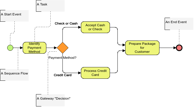
Đối với các nhà mô hình hóa cần hoặc mong muốn một mức độ chính xác thấp để tạo ra các mô hình quy trình cho mục đích tài liệu và giao tiếp, các yếu tố cốt lõi cộng với các kết nối sẽ cung cấp khả năng dễ dàng tạo ra các sơ đồ dễ hiểu (xem Sơ đồ bên dưới).
Nhấp và Mở Sơ đồ Ngay Lập Tức với Visual Paradigm Trực Tuyến)
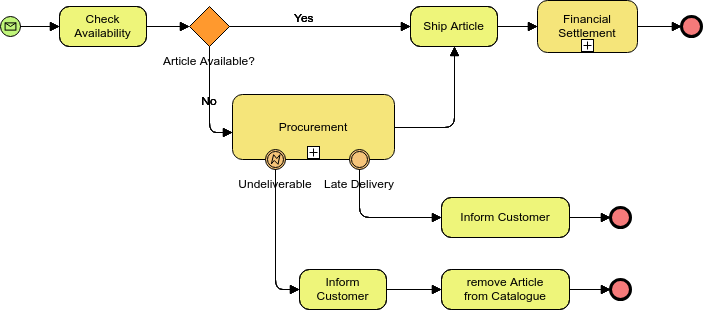
Đối với những người lập mô hình cần một mức độ chính xác cao hơn để tạo ra các mô hình quy trình, sẽ phải chịu sự phân tích chi tiết hoặc sẽ được quản lý bởi Hệ thống Quản lý Quy trình Kinh doanh (BPMS), các chi tiết bổ sung có thể được thêm vào các yếu tố cốt lõi và được hiển thị thông qua Mua sắm và Thanh toán Tài chính (xem Sơ đồ bên dưới).
(Nhấp và Mở Sơ đồ Ngay Lập Tức với Visual Paradigm Trực Tuyến
Các Làn Bơi BPMN
Nhiều phương pháp lập mô hình quy trình sử dụng khái niệm làn bơi như một cơ chế để tổ chức các hoạt động thành các danh mục hình ảnh riêng biệt nhằm minh họa các khả năng chức năng hoặc trách nhiệm khác nhau. BPMN hỗ trợ các làn bơi với hai cấu trúc chính. Hai loại đối tượng làn bơi BPD là:
- Một Pool đại diện cho một Người tham gia trong một Quy trình. Nó cũng hoạt động như một container đồ họa để phân chia một tập hợp các hoạt động từ các Pool khác, thường trong bối cảnh các tình huống B2B.
- Một Lane là một phân vùng con trong một Pool và sẽ kéo dài toàn bộ chiều dài của Pool, theo chiều dọc hoặc chiều ngang. Các Lane được sử dụng để tổ chức và phân loại các hoạt động.
Ví dụ: Quy trình Dự kiến cho Quy trình Đặt hàng dựa trên Tình trạng Hiện tại
Đây là một ví dụ về sơ đồ quy trình dự kiến. Khi quy trình kinh doanh của hoạt động hiện tại của bạn đã được tạo ra, bạn có thể suy ra mô hình quy trình dự kiến bằng cách xem xét và dự đoán các cải tiến hoặc thay đổi cần thiết phải thực hiện.
Sử dụng mẫu sơ đồ BPMN này để bắt đầu xây dựng của riêng bạn. Tùy chỉnh sơ đồ BPMN để phản ánh tổ chức của bạn.Nhấp vào Sử dụng Mẫu này để bắt đầu.
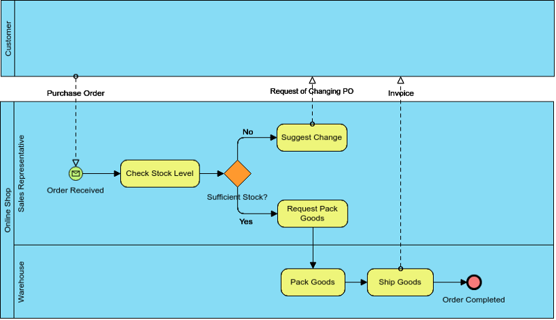
Các Pool được sử dụng khi sơ đồ liên quan đến hai thực thể kinh doanh hoặc người tham gia riêng biệt (xem Sơ đồ bên dưới) và được tách biệt về mặt vật lý trong sơ đồ. Các hoạt động trong các Pool riêng biệt được coi là các Quy trình tự chứa. Do đó, Dòng Thứ tự không thể vượt qua ranh giới của một Pool. Dòng Tin nhắn được định nghĩa là cơ chế để hiển thị sự giao tiếp giữa hai người tham gia, và do đó, phải kết nối giữa hai Pool (hoặc các đối tượng trong các Pool).
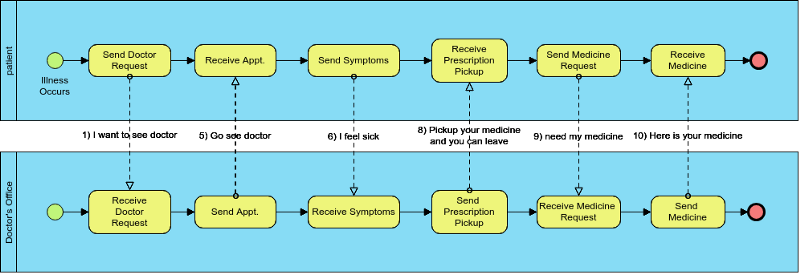
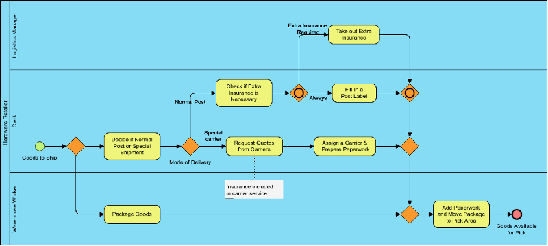
Các Lane có liên quan chặt chẽ hơn đến các phương pháp lập mô hình quy trình làn bơi truyền thống. Các Lane thường được sử dụng để tách biệt các hoạt động liên quan đến một chức năng hoặc vai trò cụ thể của công ty (xem Sơ đồ bên dưới). Dòng Thứ tự có thể vượt qua ranh giới của các Lane trong một Pool, nhưng Dòng Tin nhắn không thể được sử dụng giữa các Đối tượng Dòng trong các Lane của cùng một Pool.
Ví dụ: Quy trình Giao hàng của một Nhà bán lẻ Phần cứng
Trong ví dụ BPD này, chúng tôi chỉ sử dụng một pool và các lane khác nhau cho những người tham gia vào quy trình này, điều này tự động có nghĩa là chúng tôi bỏ qua sự giao tiếp giữa những người đó: Chúng tôi chỉ giả định rằng họ đang giao tiếp với nhau bằng cách nào đó. Nếu chúng tôi có một động cơ quy trình điều khiển quy trình này, động cơ đó sẽ phân công các nhiệm vụ cho người dùng và do đó chịu trách nhiệm về sự giao tiếp giữa những người đó.
Sử dụng mẫu sơ đồ BPMN này và tùy chỉnh nó để phản ánh tổ chức của bạn.Nhấp vào Sử dụng Mẫu này để bắt đầu.
Các Đối tượng BPMN
Các Đối tượng BPMN được thiết kế để cho phép những người lập mô hình và các công cụ lập mô hình một số linh hoạt trong việc mở rộng ký hiệu cơ bản và cung cấp khả năng thêm ngữ cảnh phù hợp với một tình huống lập mô hình cụ thể, chẳng hạn như cho một thị trường dọc (ví dụ: bảo hiểm hoặc ngân hàng). Bất kỳ số lượng Đối tượng nào có thể được thêm vào một sơ đồ phù hợp với ngữ cảnh của các quy trình kinh doanh đang được lập mô hình. Phiên bản hiện tại của đặc tả BPMN chỉ định nghĩa trước ba loại Đối tượng BPD, đó là:
Các Đối tượng Dữ liệu là một cơ chế để hiển thị cách dữ liệu được yêu cầu hoặc sản xuất bởi các hoạt động. Chúng được kết nối với các hoạt động thông qua các Liên kết.

Một Nhóm được đại diện bởi một hình chữ nhật có góc bo tròn được vẽ bằng một đường nét đứt. Việc nhóm có thể được sử dụng cho mục đích tài liệu hoặc phân tích, nhưng không ảnh hưởng đến Dòng Thứ tự.

Chú thích là một cơ chế cho một người lập mô hình cung cấp thông tin văn bản bổ sung cho người đọc Sơ đồ BPMN

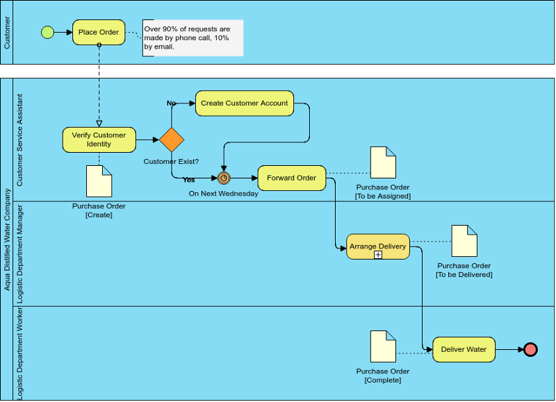
Ví dụ: Công ty Nước cất Aqua
Đây là một ví dụ BPMN đơn giản cho thấy quy trình kinh doanh liên quan đến việc cung cấp nước cất.
Sử dụng mẫu sơ đồ BPMN này làm điểm khởi đầu để tạo của riêng bạn, hoặc nhấp vào Tạo Trống để bắt đầu từ đầu.Nhấp để Mở / Chỉnh sửa Ví dụ)
Các Công Cụ Phân Tích Kinh Doanh Khác
- ArchiMate 3
- ArchiMate là gì?
- Hướng Dẫn Toàn Diện Về Các Quan Điểm ArchiMate
- Cập Nhật ArchiMate 3
- Có Gì Mới Trong ArchiMate 3?
- Sử Dụng Công Cụ ArchiMate Với TOGAF ADM
Mô Hình Hóa Quy Trình Kinh Doanh
Lập Bản Đồ Hành Trình Khách Hàng
Phần Mềm Vẽ Sơ Đồ Kinh Doanh
This post is also available in Deutsch, English, Español, فارسی, Français, Bahasa Indonesia, 日本語, Polski, Portuguese, Ру́сский, 简体中文 and 繁體中文.


